Lexus RX (RX 350L, RX450h) 2016-2026 Repair Manual: Replacement
REPLACEMENT
CAUTION / NOTICE / HINT
The necessary procedures (adjustment, calibration, initialization or registration) that must be performed after parts are removed and installed, or replaced during fuel filter removal/installation are shown below.
Necessary Procedures After Parts Removed/Installed/Replaced| Replaced Part or Performed Procedure | Necessary Procedure | Effect/Inoperative Function when Necessary Procedure not Performed | Link |
|---|---|---|---|
|
*1: When performing learning using the Techstream.
Click here | |||
| Battery terminal is disconnected/reconnected | Memorize steering angle neutral point | Lane Control System | |
| Intelligent clearance sonar system*1 | |||
| Pre-collision system | |||
| Lighting system (w/ Automatic Headlight Beam Level Control System) | | ||
| Parking assist monitor system | | ||
| Panoramic view monitor system | | ||
| Initialize back door lock | Power door lock control system | | |
| Reset back door close position | Power Back Door System (w/ Outside Door Control Switch) | | |
| Replacement of fuel pump | Inspection After Repair |
| |
NOTICE:
- Do not disconnect the tube shown in the illustration when disassembling the fuel suction tube with pump and gauge assembly. Doing so will cause reassembly of the fuel suction tube with pump and gauge assembly to be impossible as the tube is pressed into the fuel suction plate sub-assembly.
- When replacing the fuel filter, replace it together with the fuel suction plate sub-assembly.
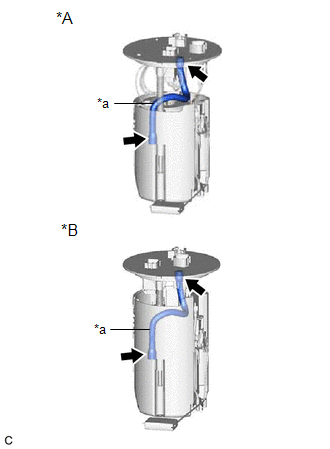
| *A | for TMC Made |
| *B | for TMMC Made |
| *a | Tube |
PROCEDURE
1. REMOVE FUEL SUCTION TUBE WITH PUMP AND GAUGE ASSEMBLY
-
for TMC Made:
Click here
.gif)
-
for TMMC Made:
Click here
2. REMOVE FUEL SENDER GAUGE ASSEMBLY
Click here
3. REMOVE FUEL SUCTION PLATE SUB-ASSEMBLY
-
for TMC Made:
Click here
-
for TMMC Made:
Click here
4. REMOVE FUEL PUMP FILTER
-
for TMC Made:
Click here
-
for TMMC Made:
Click here
5. REMOVE FUEL PUMP
-
for TMC Made:
Click here
-
for TMMC Made:
Click here
6. REMOVE FUEL MAIN VALVE ASSEMBLY
Click here
7. REMOVE NO. 1 FUEL SUCTION SUPPORT
| (a) Using a screwdriver with its tip wrapped with protective tape, disengage the 2 claws and remove the No. 1 fuel suction support from the fuel filter. |
|
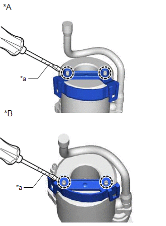
8. INSTALL NO. 1 FUEL SUCTION SUPPORT
(a) Engage the 2 claws to install the No. 1 fuel suction support to the fuel filter.
9. INSTALL FUEL MAIN VALVE ASSEMBLY
Click here
10. INSTALL FUEL PUMP
-
for TMC Made:
Click here
-
for TMMC Made:
Click here
11. INSTALL FUEL PUMP FILTER
-
for TMC Made:
Click here
-
for TMMC Made:
Click here
12. INSTALL FUEL SUCTION PLATE SUB-ASSEMBLY
-
for TMC Made:
Click here
-
for TMMC Made:
Click here
13. INSTALL FUEL SENDER GAUGE ASSEMBLY
Click here
14. INSTALL FUEL SUCTION TUBE WITH PUMP AND GAUGE ASSEMBLY
-
for TMC Made:
Click here
-
for TMMC Made:
Click here
 Components
COMPONENTS ILLUSTRATION *A for TMC Made - - *1 FUEL PUMP *2 FUEL SUCTION PLATE SUB-ASSEMBLY *3 FUEL SENDER GAUGE ASSEMBLY *4 FUEL FILTER *5 FUEL PUMP FILTER *6 ...

Other materials:
Lexus RX (RX 350L, RX450h) 2016-2026 Repair Manual > Fuel Pump (for Tmmc Made): Installation
INSTALLATION PROCEDURE 1. INSTALL FUEL SUCTION TUBE WITH PUMP AND GAUGE ASSEMBLY (a) Install a new fuel suction tube set gasket to the fuel tank assembly. (b) Set the fuel suction tube with pump and gauge assembly to the fuel tank assembly. NOTICE: Be careful not to bend the arm of the fuel sende ...
Lexus RX (RX 350L, RX450h) 2016-2026 Repair Manual > Generator (for 150 A Type): Removal
REMOVAL CAUTION / NOTICE / HINT The necessary procedures (adjustment, calibration, initialization or registration) that must be performed after parts are removed and installed, or replaced during generator assembly removal/installation are shown below. Necessary Procedures After Parts Removed/Instal ...
Lexus RX (RX 350L, RX450h) 2016-{YEAR} Owners Manual
- For your information
- Pictorial index
- For safety and security
- Instrument cluster
- Operation of each component
- Driving
- Lexus Display Audio system
- Interior features
- Maintenance and care
- When trouble arises
- Vehicle specifications
- For owners
Lexus RX (RX 350L, RX450h) 2016-{YEAR} Repair Manual

0.0108