Lexus RX (RX 350L, RX450h) 2016-2026 Repair Manual: Pressure Sensor Circuit (B1423/23)
DESCRIPTION
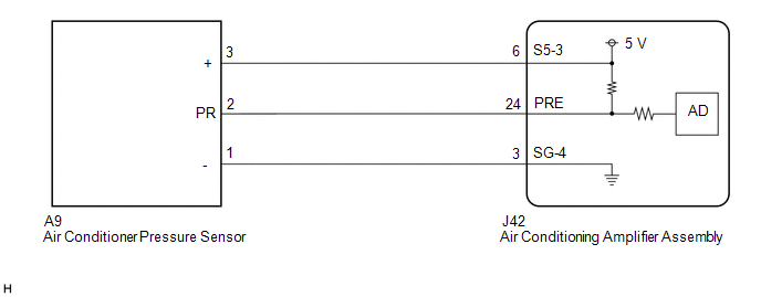
This DTC is stored if refrigerant pressure on the high pressure side is extremely low (196 kPa (2.0 kgf/cm2, 28 psi) or less) or extremely high (2812 kPa (28.7 kgf/cm2, 408 psi) or more). The air conditioner pressure sensor, which is installed to the high pressure side pipe to detect refrigerant pressure, sends a refrigerant pressure signal to the air conditioning amplifier assembly. The air conditioning amplifier assembly converts this signal to a pressure value according to the sensor characteristics and uses it to control the compressor.
| DTC No. | Detection Item | DTC Detection Condition | Trouble Area | Memory |
|---|---|---|---|---|
| B1423/23 | Pressure Sensor Circuit |
|
| - |
WIRING DIAGRAM
CAUTION / NOTICE / HINT
HINT:
If DTC B1423/23 and B14B8 are output at the same time, troubleshoot for DTC B1423/23 first.
PROCEDURE
| 1. | CHECK HARNESS AND CONNECTOR (POWER SOURCE CIRCUIT) |
(a) Disconnect the A9 air conditioner pressure sensor connector.
(b) Measure the voltage according to the value(s) in the table below.
Standard Voltage:
| Tester Connection | Condition | Specified Condition |
|---|---|---|
| A9-3 (+) - A9-1 (-) | Engine switch on (IG) | 4.75 to 5.25 V |
| NG | .gif) | GO TO STEP 16 |
|
.gif)
| 2. | INSPECT AIR CONDITIONER PRESSURE SENSOR (SENSOR SIGNAL CIRCUIT) |
(a) Reconnect the A9 air conditioner pressure sensor connector.
(b) Remove the air conditioning amplifier assembly with the connectors still connected.
| (c) Measure the voltage according to the value(s) in the table below. Standard Voltage:
HINT: If the result is not as specified, there may be a malfunction in the air conditioning amplifier assembly, air conditioner pressure sensor, or wire harness. It is also possible that the amount of refrigerant may not be appropriate. |
|
| NG | | GO TO STEP 10 |
|
| 3. | INSPECT AIR CONDITIONER PRESSURE SENSOR (SENSOR SIGNAL CIRCUIT) |
(a) Measure the voltage when the following conditions are met.
Measurement Condition:| Item | Condition |
|---|---|
| Vehicle doors | Fully open |
| Temperature setting | MAX COLD |
| Blower speed | HI |
| A/C switch | On |
| Recirculation/fresh switch | RECIRCULATION |
| Interior temperature | 25 to 35°C (77 to 95°F) |
| Engine speed | 2000 rpm |
NOTICE:
- If refrigerant pressure on the high pressure side becomes extremely high during the inspection (if the voltage exceeds 4.61 V), the fail-safe function stops compressor operation. Therefore, measure the voltage before the fail-safe operation.
- It is necessary to measure the voltage for a certain amount of time (approximately 10 minutes) because the malfunction may recur after a while.
HINT:
When the outside air temperature is low (below -1.5°C (29.3°F)), the compressor stops due to operation of the cooler (ambient temp. sensor) thermistor and the No. 1 cooler thermistor to prevent the evaporator from freezing. In this case, perform the inspection in a warm indoor environment.
| (1) Measure the voltage according to the value(s) in the table below. Standard Voltage:
|
|
| A | | REPLACE AIR CONDITIONING AMPLIFIER ASSEMBLY |
| B | | PROCEED TO NEXT SUSPECTED AREA SHOWN IN PROBLEM SYMPTOMS TABLE |
|
| 4. | INSPECT COOLING FAN SYSTEM |
(a) Check if the cooling fan operates normally.
Click here .gif)
| NG | | GO TO COOLING FAN SYSTEM |
|
| 5. | CHARGE SYSTEM WITH REFRIGERANT |
(a) Use a refrigerant recovery unit to recover refrigerant.
(b) Evacuate the air conditioning system.
(c) Add an appropriate amount of refrigerant.
Click here
HINT:
If refrigerant is added and the system has not been properly evacuated (insufficient vacuum time), moisture in the air remaining in the system will freeze in the cooler expansion valve, blocking the flow on the high pressure side. Therefore, in order to confirm the problem, recover the refrigerant and properly evacuate the system. Add an appropriate amount of refrigerant, and check for the DTC.
|
| 6. | RECHECK FOR DTC |
(a) Recheck for the DTC when the following conditions are met.
Measurement Condition:| Item | Condition |
|---|---|
| Vehicle doors | Fully open |
| Temperature setting | MAX COLD |
| Blower speed | HI |
| A/C switch | On |
| Recirculation/fresh switch | RECIRCULATION |
| Interior temperature | 25 to 35°C (77 to 95°F) |
| Engine speed | 2000 rpm |
NOTICE:
If refrigerant pressure on the high pressure side becomes high, the DTC will be stored. It is necessary to operate the air conditioning system for a certain amount of time (approximately 10 minutes) because the DTC may be stored after the air conditioning operates for a while.
HINT:
- When the outside air temperature is low (below -1.5°C (29.3°F)), the compressor stops due to operation of the cooler (ambient temp. sensor) thermistor and the No. 1 cooler thermistor to prevent the evaporator from freezing. In this case, perform the inspection in a warm indoor environment.
- If refrigerant is added and the system has not been properly evacuated (insufficient vacuum time), moisture in the air remaining in the system will freeze in the cooler expansion valve, blocking the flow on the high pressure side. Therefore, in order to confirm the problem, recover the refrigerant and properly evacuate the system. Add an appropriate amount of refrigerant, and check for the DTC. If the DTC is not output after this work, it indicates that the cooler dryer in the cooler condenser assembly is not able to absorb moisture in the refrigerant cycle. It is necessary to replace the cooler dryer in order to complete the repair.
| Result | Proceed to |
|---|---|
| DTC B1423/23 is output | A |
| DTC B1423/23 is not output | B |
| B | | REPLACE COOLER CONDENSER ASSEMBLY |
|
| 7. | REPLACE COOLER EXPANSION VALVE |
(a) Replace the cooler expansion valve with a new one.
Click here
HINT:
Replace the cooler expansion valve with a new one because the cooler expansion valve is either stuck or clogged.
|
| 8. | CHARGE SYSTEM WITH REFRIGERANT |
(a) Use a refrigerant recovery unit to recover refrigerant.
(b) Evacuate the air conditioning system.
(c) Add an appropriate amount of refrigerant.
Click here
HINT:
If refrigerant is added and the system has not been properly evacuated (insufficient vacuum time), moisture in the air remaining in the system will freeze in the cooler expansion valve, blocking the flow on the high pressure side. Therefore, in order to confirm the problem, recover the refrigerant and properly evacuate the system. Add an appropriate amount of refrigerant, and check for the DTC.
|
| 9. | RECHECK FOR DTC |
(a) Recheck for the DTC when the following conditions are met.
Measurement Condition:| Item | Condition |
|---|---|
| Vehicle doors | Fully open |
| Temperature setting | MAX COLD |
| Blower speed | HI |
| A/C switch | On |
| Recirculation/fresh switch | RECIRCULATION |
| Interior temperature | 25 to 35°C (77 to 95°F) |
| Engine speed | 2000 rpm |
NOTICE:
If refrigerant pressure on the high pressure side becomes high, the DTC will be stored. It is necessary to operate the air conditioning system for a certain amount of time (approximately 10 minutes) because the DTC may be stored after the air conditioning operates for a while.
HINT:
- When the outside air temperature is low (below -1.5°C (29.3°F)), the compressor stops due to operation of the cooler (ambient temp. sensor) thermistor and the No. 1 cooler thermistor to prevent the evaporator from freezing. In this case, perform the inspection in a warm indoor environment.
- If refrigerant pressure is not normal after replacing the cooler expansion valve with a new or known good one, the cooler condenser assembly or pipes may be clogged due to dirt, dust or other foreign matter. In this case, clean or replace the cooler condenser assembly or pipes.
| Result | Proceed to |
|---|---|
| DTC B1423/23 is not output | A |
| DTC B1423/23 is output | B |
| A | | END |
| B | | CLEAN OR REPLACE COOLER CONDENSER ASSEMBLY OR PIPE |
| 10. | CHECK HARNESS AND CONNECTOR (AIR CONDITIONING AMPLIFIER ASSEMBLY - AIR CONDITIONER PRESSURE SENSOR) |
(a) Disconnect the A9 air conditioner pressure sensor connector.
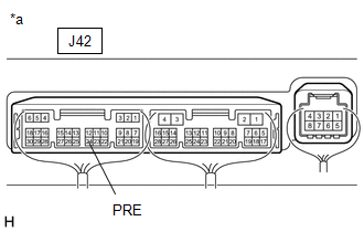
(b) Disconnect the J42 air conditioning amplifier assembly connector.
(c) Measure the resistance according to the value(s) in the table below.
Standard Resistance:
| Tester Connection | Condition | Specified Condition |
|---|---|---|
| A9-2 (PR) - J42-24 (PRE) | Always | Below 1 Ω |
| J42-24 (PRE) or A9-2 (PR) - Body ground | Always | 10 kΩ or higher |
| NG | | REPAIR OR REPLACE HARNESS OR CONNECTOR |
|
| 11. | INSPECT FOR AIR CONDITIONING SYSTEM LEAK |
(a) Install a manifold gauge set.
(b) Recover the refrigerant from the air conditioning system using a refrigerant recovery unit.
(c) Evacuate the air conditioning system and check that vacuum can be maintained.
OK:
Vacuum can be maintained in the air conditioning system.
HINT:
If vacuum cannot be maintained in the air conditioning system, refrigerant may be leaking from it. In this case, it is necessary to repair or replace the leaking part of the air conditioning system.
| NG | | GO TO STEP 15 |
|
| 12. | CHARGE SYSTEM WITH REFRIGERANT |
(a) Use a refrigerant recovery unit to recover refrigerant.
(b) Evacuate the air conditioning system.
(c) Add an appropriate amount of refrigerant.
Click here
HINT:
If refrigerant is added and the system has not been properly evacuated (insufficient vacuum time), moisture in the air remaining in the system will freeze in the cooler expansion valve, blocking the flow on the high pressure side. Therefore, in order to confirm the problem, recover the refrigerant and properly evacuate the system. Add an appropriate amount of refrigerant, and check for the DTC.
|
| 13. | RECHECK FOR DTC |
(a) Recheck for the DTC when the following conditions are met.
Measurement Condition:| Item | Condition |
|---|---|
| Vehicle doors | Fully open |
| Temperature setting | MAX COLD |
| Blower speed | HI |
| A/C switch | On |
| Recirculation/fresh switch | RECIRCULATION |
| Interior temperature | 25 to 35°C (77 to 95°F) |
| Engine speed | 2000 rpm |
NOTICE:
If refrigerant pressure on the high pressure side becomes high, the DTC will be stored. It is necessary to operate the air conditioning system for a certain amount of time (approximately 10 minutes) because the DTC may be stored after the air conditioning operates for a while.
HINT:
When the outside air temperature is low (below -1.5°C (29.3°F)), the compressor stops due to operation of the cooler (ambient temp. sensor) thermistor and the No. 1 cooler thermistor to prevent the evaporator from freezing. In this case, perform the inspection in a warm indoor environment.
| Result | Proceed to |
|---|---|
| DTC B1423/23 is output | A |
| DTC B1423/23 is not output | B |
NOTICE:
If the DTC was stored to an insufficient or excessive amount of refrigerant, the problem may have been solved after performing the previous step. However, the root cause of insufficient refrigerant may be refrigerant leaks. The root cause of excessive refrigerant may be adding too much refrigerant when the level was insufficient. Therefore, identify and repair the area where refrigerant leaks from as necessary.
| B | | END |
|
| 14. | INSPECT AIR CONDITIONER PRESSURE SENSOR |
(a) Install a manifold gauge set.
(b) Reconnect the A9 air conditioner pressure sensor connector.
(c) Turn the engine switch on (IG).
| (d) Measure the voltage according to the value(s) in the table below. Standard Voltage:
|
|
.png)
| OK | | REPLACE AIR CONDITIONING AMPLIFIER ASSEMBLY |
| NG | | REPLACE AIR CONDITIONER PRESSURE SENSOR |
| 15. | REPAIR AIR CONDITIONING SYSTEM LEAK |
(a) Identify the area where refrigerant leaks from.
Click here
(b) Repair the identified area of the air conditioning system.
(c) Evacuate the air conditioning system.
| NEXT | | CHARGE SYSTEM WITH REFRIGERANT |
| 16. | CHECK HARNESS AND CONNECTOR (AIR CONDITIONING AMPLIFIER ASSEMBLY - AIR CONDITIONER PRESSURE SENSOR) |
(a) Disconnect the J42 air conditioning amplifier assembly connector.
(b) Measure the resistance according to the value(s) in the table below.
Standard Resistance:
| Tester Connection | Condition | Specified Condition |
|---|---|---|
| A9-3 (+) - J42-6 (S5-3) | Always | Below 1 Ω |
| J42-6 (S5-3) or A9-3 (+) - Body ground | Always | 10 kΩ or higher |
| OK | | REPLACE AIR CONDITIONING AMPLIFIER ASSEMBLY |
| NG | | REPAIR OR REPLACE HARNESS OR CONNECTOR |
 Compressor Lock Sensor Circuit (B1422/22)
DESCRIPTION The ECM sends the engine speed signal to the air conditioning amplifier assembly via CAN communication. The air conditioning amplifier assembly reads the difference between compressor spee ...
 Air Mix Damper Control Servo Motor Circuit (Passenger Side) (B1441/41)
DESCRIPTION The No. 1 air conditioning radiator damper servo sub-assembly (front passenger side air mix) sends pulse signals to inform the air conditioning amplifier assembly of the damper position. T ...
Other materials:
Lexus RX (RX 350L, RX450h) 2016-2026 Repair Manual > Rear No. 1 Seat Assembly (for 60/40 Split Seat Type Rh Side): Components
COMPONENTS ILLUSTRATION *1 REAR DOOR SCUFF PLATE RH *2 REAR NO. 1 SEAT ASSEMBLY RH *3 REAR SEAT CENTER HEADREST ASSEMBLY *4 REAR SEAT HEADREST ASSEMBLY *5 REAR SEAT INNER TRACK BRACKET COVER RH *6 REAR SEAT OUTER TRACK BRACKET COVER RH *7 REAR SEAT OUTER TRACK BRA ...
Lexus RX (RX 350L, RX450h) 2016-2026 Owners Manual > Before driving: Trailer towing (vehicles
with towing package)
Your vehicle is designed primarily as a passenger-and-load-carrying
vehicle.
Towing a trailer can have an adverse impact on handling, performance, braking,
durability, and fuel consumption. For your safety and the safety of others,
you must not overload your vehicle or trailer. You must also ...
Lexus RX (RX 350L, RX450h) 2016-{YEAR} Owners Manual
- For your information
- Pictorial index
- For safety and security
- Instrument cluster
- Operation of each component
- Driving
- Lexus Display Audio system
- Interior features
- Maintenance and care
- When trouble arises
- Vehicle specifications
- For owners
Lexus RX (RX 350L, RX450h) 2016-{YEAR} Repair Manual

0.0153