Lexus RX (RX 350L, RX450h) 2016-2026 Repair Manual: Compressor Lock Sensor Circuit (B1422/22)
DESCRIPTION
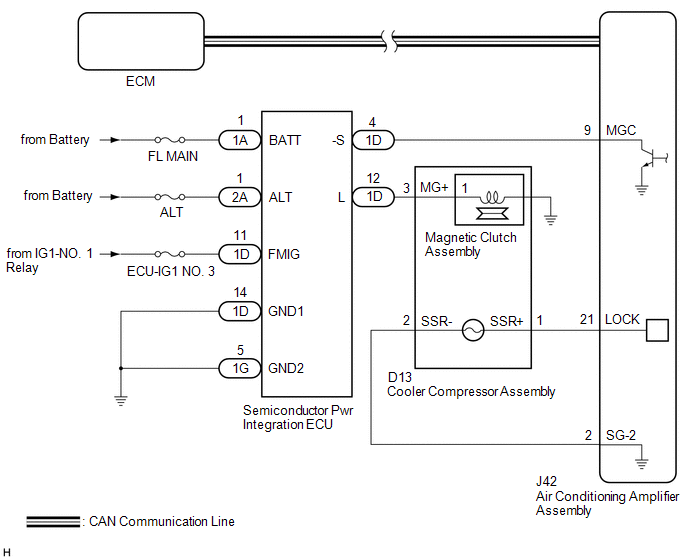
The ECM sends the engine speed signal to the air conditioning amplifier assembly via CAN communication.
The air conditioning amplifier assembly reads the difference between compressor speed and engine speed. When the difference becomes too large, the air conditioning amplifier assembly determines that the compressor is locked, and turns the magnetic clutch assembly off.
| DTC No. | Detection Item | DTC Detection Condition | Trouble Area | Memory |
|---|---|---|---|---|
| B1422/22 | Compressor Lock Sensor Circuit | Open or short in A/C lock sensor circuit |
| Memorized (3 sec. or more)* |
- *: The air conditioning amplifier assembly stores this DTC if the malfunction has occurred for the period of time indicated in the brackets.
WIRING DIAGRAM
CAUTION / NOTICE / HINT
NOTICE:
ECM malfunctions can affect the storage of this DTC. Therefore, check all SFI system DTCs and confirm that the system is normal before performing the following inspection.
Click here .gif)
PROCEDURE
| 1. | CHECK CAN COMMUNICATION SYSTEM |
(a) Using the Techstream, check if the CAN communication system is functioning normally.
Click here
| Result | Proceed to |
|---|---|
| CAN communication system DTCs are not output | A |
| CAN communication system DTCs are output | B |
| B | .gif) | GO TO CAN COMMUNICATION SYSTEM |
|
.gif)
| 2. | PERFORM ACTIVE TEST USING TECHSTREAM |
(a) Disconnect the magnetic clutch assembly connector.
(b) Install SST to the connector on the magnetic clutch relay side.
SST: 09843-18040
(c) Connect the Techstream to the DLC3.
(d) Start the engine.
(e) Turn the Techstream on.
(f) Enter the following menus: Body Electrical / Air Conditioner / Active Test.
Body Electrical > Air Conditioner > Active Test| Tester Display | Measurement Item | Control Range | Diagnostic Note |
|---|---|---|---|
| Magnetic Clutch Relay | Air conditioning system operation | OFF, ON | - |
| (g) Measure the voltage according to the value(s) in the table below. Standard Voltage:
HINT: When performing the Active Test, voltage between 11 and 14 V is output for approximately 3 seconds. |
|
| NG | | GO TO AIR CONDITIONING COMPRESSOR MAGNETIC CLUTCH CIRCUIT |
|
| 3. | INSPECT MAGNETIC CLUTCH ASSEMBLY |
(a) Connect the magnetic clutch assembly connector.
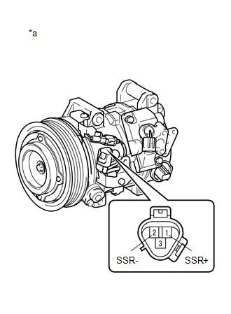
(b) Disconnect the D13 cooler compressor assembly connector.
| (c) Measure the resistance according to the value(s) in the table below. Standard Resistance:
|
|
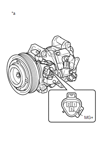
(d) Connect a positive (+) lead from the battery to terminal 3 (MG+) and check that the following occurs: 1) the magnetic clutch assembly operating sound can be heard, and 2) the magnetic clutch hub and rotor lock.
| NG | | REPLACE MAGNETIC CLUTCH ASSEMBLY |
|
| 4. | INSPECT COOLER COMPRESSOR ASSEMBLY |
| (a) Measure the resistance according to the value(s) in the table below. Standard Resistance:
|
|
| NG | | REPLACE COOLER COMPRESSOR ASSEMBLY |
|
| 5. | CHECK HARNESS AND CONNECTOR (COOLER COMPRESSOR ASSEMBLY - AIR CONDITIONING AMPLIFIER ASSEMBLY) |
(a) Disconnect the J42 air conditioning amplifier assembly connector.
(b) Measure the resistance according to the value(s) in the table below.
Standard Resistance:
| Tester Connection | Condition | Specified Condition |
|---|---|---|
| D13-1 (SSR+) - J42-21 (LOCK) | Always | Below 1 Ω |
| D13-2 (SSR-) - J42-2 (SG-2) | Always | Below 1 Ω |
| J42-21 (LOCK) or D13-1 (SSR+) - Body ground | Always | 10 kΩ or higher |
| J42-2 (SG-2) or D13-2 (SSR-) - Body ground | Always | 10 kΩ or higher |
| Result | Proceed to |
|---|---|
| NG | A |
| OK (When troubleshooting according to Problem Symptoms Table) | B |
| OK (When troubleshooting according to the DTC) | C |
| A | | REPAIR OR REPLACE HARNESS OR CONNECTOR |
| B | | PROCEED TO NEXT SUSPECTED AREA SHOWN IN PROBLEM SYMPTOMS TABLE |
| C | | REPLACE AIR CONDITIONING AMPLIFIER ASSEMBLY |
 Rear Room Temperature Sensor Circuit (B1419/19)
DESCRIPTION The cooler (No. 2 room temp. sensor) thermistor is installed in the rear panel to detect the rear cabin temperature, which is used to control the air conditioning system. The resistance of ...
 Pressure Sensor Circuit (B1423/23)
DESCRIPTION This DTC is stored if refrigerant pressure on the high pressure side is extremely low (196 kPa (2.0 kgf/cm2, 28 psi) or less) or extremely high (2812 kPa (28.7 kgf/cm2, 408 psi) or more). ...
Other materials:
Lexus RX (RX 350L, RX450h) 2016-2026 Repair Manual > Fuel Sender Gauge Assembly: Components
COMPONENTS ILLUSTRATION *A for TMC Made - - *1 FUEL SENDER GAUGE ASSEMBLY *2 FUEL SUCTION TUBE WITH PUMP AND GAUGE ASSEMBLY ILLUSTRATION *A for TMMC Made - - *1 FUEL SENDER GAUGE ASSEMBLY *2 FUEL SUCTION TUBE WITH PUMP AND GAUGE ASSEMBLY ...
Lexus RX (RX 350L, RX450h) 2016-2026 Repair Manual > Front Door Window Frame Moulding: Removal
REMOVAL CAUTION / NOTICE / HINT The necessary procedures (adjustment, calibration, initialization or registration) that must be performed after parts are removed and installed, or replaced during front door window frame moulding removal/installation are shown below. Necessary Procedures After Parts ...
Lexus RX (RX 350L, RX450h) 2016-{YEAR} Owners Manual
- For your information
- Pictorial index
- For safety and security
- Instrument cluster
- Operation of each component
- Driving
- Lexus Display Audio system
- Interior features
- Maintenance and care
- When trouble arises
- Vehicle specifications
- For owners
Lexus RX (RX 350L, RX450h) 2016-{YEAR} Repair Manual

0.0127