Lexus RX (RX 350L, RX450h) 2016-2026 Repair Manual: Rear Room Temperature Sensor Circuit (B1419/19)
DESCRIPTION
The cooler (No. 2 room temp. sensor) thermistor is installed in the rear panel to detect the rear cabin temperature, which is used to control the air conditioning system. The resistance of the cooler (No. 2 room temp. sensor) thermistor changes in accordance with the rear cabin temperature. As the temperature decreases, the resistance increases. As the temperature increases, the resistance decreases.
The air conditioning amplifier assembly applies voltage (5 V) to the cooler (No. 2 room temp. sensor) thermistor and reads voltage changes due to changes in the resistance of the cooler (No. 2 room temp. sensor) thermistor.
| DTC No. | Detection Item | DTC Detection Condition | Trouble Area | Memory |
|---|---|---|---|---|
| B1419/19 | Rear Room Temperature Sensor Circuit | Open or short in rear room temperature sensor circuit |
| Memorized (4 sec. or more)*1 |
- *1: The air conditioning amplifier assembly stores this DTC if the malfunction has occurred for the period of time indicated in the brackets.
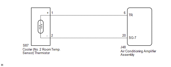
WIRING DIAGRAM
PROCEDURE
| 1. | READ VALUE USING TECHSTREAM |
(a) Connect the Techstream to the DLC3.
(b) Turn the engine switch on (IG).
(c) Turn the Techstream on.
(d) Enter the following menus: Body Electrical / Air Conditioner / Data List.
(e) Check the value(s) by referring to the table below.
Body Electrical > Air Conditioner > Data List| Tester Display | Measurement Item | Range | Normal Condition | Diagnostic Note |
|---|---|---|---|---|
| Room Temp Sensor (Rear) | Cooler (No. 2 room temp. sensor) thermistor | Min.: -6.50°C (20.30°F) Max.: 57.25°C (135.05°F) | Actual rear cabin temperature displayed | - |
| Tester Display |
|---|
| Room Temp Sensor (Rear) |
OK:
The display is as specified in the normal condition column.
| Result | Proceed to |
|---|---|
| OK (When troubleshooting according to Problem Symptoms Table) | A |
| OK (When troubleshooting according to the DTC) | B |
| NG | C |
| A | .gif) | PROCEED TO NEXT SUSPECTED AREA SHOWN IN PROBLEM SYMPTOMS TABLE |
| B | | REPLACE AIR CONDITIONING AMPLIFIER ASSEMBLY |
|
.gif)
| 2. | INSPECT COOLER (NO. 2 ROOM TEMP. SENSOR) THERMISTOR |
(a) Remove the cooler (No. 2 room temp. sensor) thermistor.
Click here .gif)
(b) Inspect the cooler (No. 2 room temp. sensor) thermistor.
Click here
| NG | | REPLACE COOLER (NO. 2 ROOM TEMP. SENSOR) THERMISTOR |
|
| 3. | CHECK HARNESS AND CONNECTOR (COOLER (NO. 2 ROOM TEMP. SENSOR) THERMISTOR - AIR CONDITIONING AMPLIFIER ASSEMBLY) |
(a) Disconnect the J48 air conditioning amplifier assembly connector.
(b) Measure the resistance according to the value(s) in the table below.
Standard Resistance:
| Tester Connection | Condition | Specified Condition |
|---|---|---|
| S87-1 (+) - J48-6 (TR) | Always | Below 1 Ω |
| S87-2 (-) - J48-20 (SG-7) | Always | Below 1 Ω |
| S87-1 (+) or J48-6 (TR) - Other terminals and body ground | Always | 10 kΩ or higher |
| S87-2 (-) or J48-20 (SG-7) - Other terminals and body ground | Always | 10 kΩ or higher |
| OK | | REPLACE AIR CONDITIONING AMPLIFIER ASSEMBLY |
| NG | | REPAIR OR REPLACE HARNESS OR CONNECTOR |
 Exhaust Gas Sensor Circuit (B1418/18)
DESCRIPTION The smog ventilation sensor is installed to the front of the cooler condenser assembly to automatically control the air inlet mode (fresh, recirculation/fresh, and recirculation). This sen ...
 Compressor Lock Sensor Circuit (B1422/22)
DESCRIPTION The ECM sends the engine speed signal to the air conditioning amplifier assembly via CAN communication. The air conditioning amplifier assembly reads the difference between compressor spee ...
Other materials:
Lexus RX (RX 350L, RX450h) 2016-2026 Repair Manual > Dynamic Radar Cruise Control System: Road Test
ROAD TEST HINT:
The dynamic radar cruise control system has 2 cruise control modes: constant speed control mode and vehicle-to-vehicle distance control mode.
Vehicle-to-vehicle distance control mode is selected by default when the dynamic radar cruise control system is turned on using the cruis ...
Lexus RX (RX 350L, RX450h) 2016-2026 Repair Manual > Steering Lock System: Parts Location
PARTS LOCATION ILLUSTRATION *1 FRONT DOOR COURTESY LIGHT SWITCH ASSEMBLY LH *2 ENGINE ROOM RELAY BLOCK AND JUNCTION BLOCK ASSEMBLY - IG2 RELAY - IG2-MAIN FUSE - ECU-IG2 NO. 1 FUSE ILLUSTRATION *1 MAIN BODY ECU (MULTIPLEX NETWORK BODY ECU) *2 ID CODE BOX (IMMOBILISER CODE ECU) ...
Lexus RX (RX 350L, RX450h) 2016-{YEAR} Owners Manual
- For your information
- Pictorial index
- For safety and security
- Instrument cluster
- Operation of each component
- Driving
- Lexus Display Audio system
- Interior features
- Maintenance and care
- When trouble arises
- Vehicle specifications
- For owners
Lexus RX (RX 350L, RX450h) 2016-{YEAR} Repair Manual

0.0121