Lexus RX (RX 350L, RX450h) 2016-2026 Repair Manual: PTC Heater Circuit
DESCRIPTION
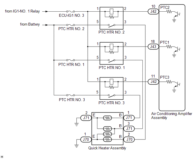
The air conditioning amplifier assembly sends operation signals to the PTC heater relays when quick heater assembly operation conditions are met. Based on the signals from the air conditioning amplifier assembly, the PTC heater relays turn on, and power is supplied to the quick heater assembly installed in the air conditioning radiator assembly.
Quick Heater Assembly Operation Condition| Control ECU | Condition |
|---|---|
| Air Conditioning Amplifier Assembly | Engine running |
| Combination switch assembly (ECO mode switch) off | |
| Blower switch: On | |
| Temperature setting: MAX HOT | |
| Light control switch off | |
| |
|
WIRING DIAGRAM
CAUTION / NOTICE / HINT
NOTICE:
-
If the battery voltage is low, the PTC heater may not operate. When "Operation of Electrical Items Restricted." is displayed on the multi-information display in the combination meter assembly, inspect the battery, referring to On-vehicle Inspection for the charging system.
Click here
.gif)
-
If the battery voltage is low, the PTC heater may not operate. When "Operation of Electrical Items Restricted." is not displayed on the multi-information display in the combination meter assembly, check the Data List item "Battery Control Count (Body ECU)".
Click here
- Inspect the fuses for circuits related to this system before performing the following procedure.
PROCEDURE
| 1. | PERFORM ACTIVE TEST USING TECHSTREAM |
(a) Connect the Techstream to the DLC3.
(b) Turn the engine switch on (IG).
(c) Turn the Techstream on.
(d) Enter the following menus: Body Electrical / Air Conditioner / Active Test.
(e) Perform the Active Test according to the display on the Techstream.
Body Electrical > Air Conditioner > Active Test| Tester Display | Measurement Item | Control Range | Diagnostic Note |
|---|---|---|---|
| Heater Active Level | Quick heater assembly | Min.: 0, Max.: 3 | - |
| Tester Display |
|---|
| Heater Active Level |
OK:
Heater Active Level changes normally.
| NG | .gif) | PROCEED TO NEXT SUSPECTED AREA SHOWN IN PROBLEM SYMPTOMS TABLE |
|
.gif)
| 2. | INSPECT PTC HEATER RELAY |
(a) Remove the PTC heater relays.
(b) Measure the resistance according to the value(s) in the table below.
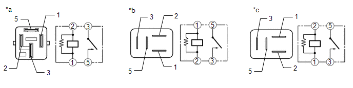
| *a | Component without harness connected (PTC HTR NO. 1) | *b | Component without harness connected (PTC HTR NO. 2) |
| *c | Component without harness connected (PTC HTR NO. 3) | - | - |
Standard Resistance:
| Tester Connection | Condition | Specified Condition |
|---|---|---|
| 3 - 5 | Battery voltage not applied between terminals 1 and 2 | 10 kΩ or higher |
| 3 - 5 | Battery voltage applied between terminals 1 and 2 | Below 1 Ω |
| NG | | REPLACE PTC HEATER RELAY |
|
| 3. | CHECK HARNESS AND CONNECTOR (PTC HEATER RELAY - POWER SOURCE) |
(a) Measure the voltage according to the value(s) in the table below.
Standard Voltage:
PTC HTR NO. 1
| Tester Connection | Condition | Specified Condition |
|---|---|---|
| Relay terminal 5 - Body ground | Always | 11 to 14 V |
| Relay terminal 1 - Body ground | Engine switch off | Below 1 V |
| Relay terminal 1 - Body ground | Engine switch on (IG) | 11 to 14 V |
Standard Voltage:
PTC HTR NO. 2
| Tester Connection | Condition | Specified Condition |
|---|---|---|
| Relay terminal 5 - Body ground | Always | 11 to 14 V |
| Relay terminal 1 - Body ground | Engine switch off | Below 1 V |
| Relay terminal 1 - Body ground | Engine switch on (IG) | 11 to 14 V |
Standard Voltage:
PTC HTR NO. 3
| Tester Connection | Condition | Specified Condition |
|---|---|---|
| Relay terminal 5 - Body ground | Always | 11 to 14 V |
| Relay terminal 1 - Body ground | Engine switch off | Below 1 V |
| Relay terminal 1 - Body ground | Engine switch on (IG) | 11 to 14 V |
| NG | | REPAIR OR REPLACE HARNESS OR CONNECTOR |
|
| 4. | CHECK HARNESS AND CONNECTOR (PTC HEATER RELAY - AIR CONDITIONING AMPLIFIER ASSEMBLY) |
(a) Disconnect the J43 and J42 air conditioning amplifier assembly connectors.
(b) Measure the resistance according to the value(s) in the table below.
Standard Resistance:
PTC HTR NO. 1
| Tester Connection | Condition | Specified Condition |
|---|---|---|
| Relay terminal 2 - J43-18 (PTC1) | Always | Below 1 Ω |
| Relay terminal 2 or J43-18 (PTC1) - Body ground | Always | 10 kΩ or higher |
Standard Resistance:
PTC HTR NO. 2
| Tester Connection | Condition | Specified Condition |
|---|---|---|
| Relay terminal 2 - J42-10 (PTC2) | Always | Below 1 Ω |
| Relay terminal 2 or J42-10 (PTC2) - Body ground | Always | 10 kΩ or higher |
Standard Resistance:
PTC HTR NO. 3
| Tester Connection | Condition | Specified Condition |
|---|---|---|
| Relay terminal 2 - J42-11 (PTC3) | Always | Below 1 Ω |
| Relay terminal 2 or J42-11 (PTC3) - Body ground | Always | 10 kΩ or higher |
| NG | | REPAIR OR REPLACE HARNESS OR CONNECTOR |
|
| 5. | CHECK HARNESS AND CONNECTOR (PTC HEATER RELAY - QUICK HEATER ASSEMBLY AND BODY GROUND) |
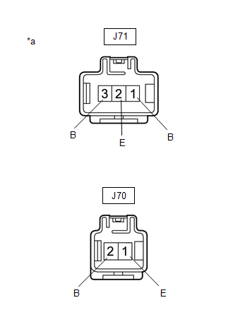
(a) Disconnect the J71 and J70 quick heater assembly connectors.
(b) Measure the resistance according to the value(s) in the table below.
Standard Resistance:
PTC HTR NO. 1
| Tester Connection | Condition | Specified Condition |
|---|---|---|
| Relay terminal 3 - J71-3 (B) | Always | Below 1 Ω |
| J71-2 (E) - Body ground | Always | Below 1 Ω |
| J70-1 (E) - Body ground | Always | Below 1 Ω |
| J71-3 (B) - Body ground | Always | 10 kΩ or higher |
Standard Resistance:
PTC HTR NO. 2
| Tester Connection | Condition | Specified Condition |
|---|---|---|
| Relay terminal 3 - J70-2 (B) | Always | Below 1 Ω |
| J70-1 (E) - Body ground | Always | Below 1 Ω |
| J70-2 (B) - Body ground | Always | 10 kΩ or higher |
Standard Resistance:
PTC HTR NO. 3
| Tester Connection | Condition | Specified Condition |
|---|---|---|
| Relay terminal 3 - J71-1 (B) | Always | Below 1 Ω |
| J71-2 (E) - Body ground | Always | Below 1 Ω |
| J71-1 (B) - Body ground | Always | 10 kΩ or higher |
| NG | | REPAIR OR REPLACE HARNESS OR CONNECTOR |
|
| 6. | INSPECT QUICK HEATER ASSEMBLY |
(a) Remove the quick heater assembly.
Click here
| (b) Measure the resistance according to the value(s) in the table below. Standard Resistance:
|
|
| OK | | REPLACE AIR CONDITIONING AMPLIFIER ASSEMBLY |
| NG | | REPLACE QUICK HEATER ASSEMBLY |
 Air Conditioning Compressor Magnetic Clutch Circuit
DESCRIPTION When the air conditioning amplifier assembly is turned on, a magnetic clutch on signal is sent from the MGC terminal of the air conditioning amplifier assembly. Then, the semiconductor pwr ...
 Rear Blower Motor Circuit
DESCRIPTION The rear blower motor with fan sub-assembly is operated by signals from the air conditioning amplifier assembly. Rear blower motor speed signals are transmitted in accordance with changes ...
Other materials:
Lexus RX (RX 350L, RX450h) 2016-2026 Repair Manual > Vehicle Stability Control System: Problem Symptoms Table
PROBLEM SYMPTOMS TABLE If there are no DTCs output and the problem still occurs, check the suspected areas for each problem symptom in the order given in the following table and proceed to the relevant troubleshooting page. NOTICE: When replacing the skid control ECU (brake actuator assembly), senso ...
Lexus RX (RX 350L, RX450h) 2016-2026 Repair Manual > Power Seat Switch(w/ Seat Position Memory System): Installation
INSTALLATION CAUTION / NOTICE / HINT CAUTION: Wear protective gloves. Sharp areas on the parts may injure your hands. PROCEDURE 1. INSTALL POSITION CONTROL ECU AND SWITCH ASSEMBLY LH (a) Install the position control ECU and switch assembly LH to the front seat cushion shield LH with the 3 screws. ...
Lexus RX (RX 350L, RX450h) 2016-{YEAR} Owners Manual
- For your information
- Pictorial index
- For safety and security
- Instrument cluster
- Operation of each component
- Driving
- Lexus Display Audio system
- Interior features
- Maintenance and care
- When trouble arises
- Vehicle specifications
- For owners
Lexus RX (RX 350L, RX450h) 2016-{YEAR} Repair Manual

0.0115