Lexus RX (RX 350L, RX450h) 2016-2026 Repair Manual: Air Conditioning Compressor Magnetic Clutch Circuit
DESCRIPTION
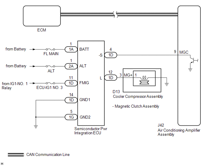
When the air conditioning amplifier assembly is turned on, a magnetic clutch on signal is sent from the MGC terminal of the air conditioning amplifier assembly. Then, the semiconductor pwr integration ECU turns on to operate the magnetic clutch assembly.
WIRING DIAGRAM
CAUTION / NOTICE / HINT
NOTICE:
-
ECM malfunctions can affect the storage of this DTC. Therefore, check all SFI system DTCs and confirm that the system is normal before performing the following inspection.
Click here
.gif)
- Inspect the fuses for circuits related to this system before performing the following procedure.
PROCEDURE
| 1. | CHECK CAN COMMUNICATION SYSTEM |
(a) Using the Techstream, check if the CAN communication system is functioning normally.
Click here
| Result | Proceed to |
|---|---|
| CAN communication system DTCs are not output | A |
| CAN communication system DTCs are output | B |
| B | .gif) | GO TO CAN COMMUNICATION SYSTEM |
|
.gif)
| 2. | CHECK SEMICONDUCTOR POWER INTEGRATION ECU |
(a) Using a voltmeter, check the signal reading of the semiconductor pwr integration ECU.
Click here
OK:
A normal signal reading is output.
| NG | | CHECK SEMICONDUCTOR POWER INTEGRATION ECU (RESULT OF SIGNAL READING) |
|
| 3. | CHECK HARNESS AND CONNECTOR (SEMICONDUCTOR PWR INTEGRATION ECU - POWER SOURCE AND BODY GROUND) |
(a) Remove the semiconductor pwr integration ECU from the engine room relay block and junction block assembly.
Click here
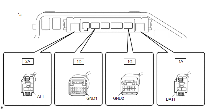
| *a | Component without Semiconductor Pwr Integration ECU (Engine Room Relay Block and Junction Block Assembly) | - | - |
(b) Measure the voltage according to the value(s) in the table below.
Standard Voltage:
| Tester Connection | Condition | Specified Condition |
|---|---|---|
| 2A-1 (ALT) - Body ground | Always | 11 to 14 V |
| 1A-1 (BATT) - Body ground | Always | 11 to 14 V |
(c) Measure the resistance according to the value(s) in the table below.
Standard Resistance:
| Tester Connection | Condition | Specified Condition |
|---|---|---|
| 1D-14 (GND1) - Body ground | Always | Below 1 Ω |
| 1G-5 (GND2) - Body ground | Always | Below 1 Ω |
| NG | | REPAIR OR REPLACE HARNESS OR CONNECTOR |
|
| 4. | CHECK HARNESS AND CONNECTOR (SEMICONDUCTOR PWR INTEGRATION ECU - COOLER COMPRESSOR ASSEMBLY) |
(a) Disconnect the D13 cooler compressor assembly connector.
(b) Measure the resistance according to the value(s) in the table below.
Standard Resistance:
| Tester Connection | Condition | Specified Condition |
|---|---|---|
| 1D-12 (L) - D13-3 (MG+) | Always | Below 1 Ω |
| 1D-12 (L) or D13-3 (MG+) - Body ground | Always | 10 kΩ or higher |
| NG | | REPAIR OR REPLACE HARNESS OR CONNECTOR |
|
| 5. | CHECK HARNESS AND CONNECTOR (SEMICONDUCTOR PWR INTEGRATION ECU - AIR CONDITIONING AMPLIFIER ASSEMBLY) |
(a) Disconnect the J42 air conditioning amplifier assembly connector.
(b) Measure the resistance according to the value(s) in the table below.
Standard Resistance:
| Tester Connection | Condition | Specified Condition |
|---|---|---|
| 1D-4 (-S) - J42-9 (MGC) | Always | Below 1 Ω |
| 1D-4 (-S) or J42-9 (MGC) - Body ground | Always | 10 kΩ or higher |
| NG | | REPAIR OR REPLACE HARNESS OR CONNECTOR |
|
| 6. | CHECK MAGNETIC CLUTCH ASSEMBLY |
| (a) Measure the resistance according to the value(s) in the table below. Standard Resistance:
|
|
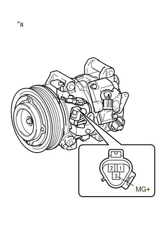
(b) Connect a positive (+) lead from the battery to terminal D13-3 (MG+) and check that the following occurs: 1) the magnetic clutch assembly operating sound can be heard, and 2) the magnetic clutch hub and rotor lock.
| OK | | PROCEED TO NEXT SUSPECTED AREA SHOWN IN PROBLEM SYMPTOMS TABLE |
| NG | | REPLACE MAGNETIC CLUTCH ASSEMBLY |
 Blower Motor Circuit
DESCRIPTION The blower motor with fan sub-assembly is operated by signals from the air conditioning amplifier assembly. Blower motor speed signals are transmitted in accordance with changes in the dut ...
 PTC Heater Circuit
DESCRIPTION The air conditioning amplifier assembly sends operation signals to the PTC heater relays when quick heater assembly operation conditions are met. Based on the signals from the air conditio ...
Other materials:
Lexus RX (RX 350L, RX450h) 2016-2026 Repair Manual > Rear Power Seat Control System(for Third Row): System Description
SYSTEM DESCRIPTION REAR POWER SEAT CONTROL SYSTEM DESCRIPTION
The rear No. 2 power seats have fold , return and jam protection functions.
Each rear No. 2 power seat can be operated independently.
FUNCTION OF MAIN COMPONENTS Component Function
No. 2 Seatback Frame Sub-assembly LH ...
Lexus RX (RX 350L, RX450h) 2016-2026 Repair Manual > Instrument Panel Speaker: Components
COMPONENTS ILLUSTRATION *A for Side *B for Center *1 FRONT NO. 2 SPEAKER ASSEMBLY *2 FRONT NO. 3 SPEAKER ASSEMBLY *3 NO. 1 INSTRUMENT PANEL SPEAKER PANEL SUB-ASSEMBLY *4 NO. 1 SPEAKER OPENING COVER ASSEMBLY ...
Lexus RX (RX 350L, RX450h) 2016-{YEAR} Owners Manual
- For your information
- Pictorial index
- For safety and security
- Instrument cluster
- Operation of each component
- Driving
- Lexus Display Audio system
- Interior features
- Maintenance and care
- When trouble arises
- Vehicle specifications
- For owners
Lexus RX (RX 350L, RX450h) 2016-{YEAR} Repair Manual

0.0091