Lexus RX (RX 350L, RX450h) 2016-2026 Repair Manual: Blower Motor Circuit
DESCRIPTION
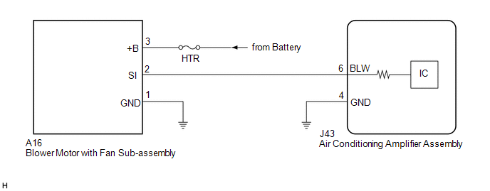
The blower motor with fan sub-assembly is operated by signals from the air conditioning amplifier assembly. Blower motor speed signals are transmitted in accordance with changes in the duty ratio.
WIRING DIAGRAM
CAUTION / NOTICE / HINT
NOTICE:
Inspect the fuses for circuits related to this system before performing the following procedure.
PROCEDURE
| 1. | PERFORM ACTIVE TEST USING TECHSTREAM |
(a) Connect the Techstream to the DLC3.
(b) Turn the engine switch on (IG).
(c) Turn the Techstream on.
(d) Enter the following menus: Body Electrical / Air Conditioner / Active Test.
(e) Perform the Active Test according to the display on the Techstream.
Body Electrical > Air Conditioner > Active Test| Tester Display | Measurement Item | Control Range | Diagnostic Note |
|---|---|---|---|
| Blower Motor | Blower motor with fan sub-assembly | Min.: 0, Max.: 31 | - |
| Tester Display |
|---|
| Blower Motor |
| Result | Proceed to |
|---|---|
| OK | A |
| NG (Blower motor with fan sub-assembly does not operate) | B |
| NG (Blower motor with fan sub-assembly operates but does not change speed) | C |
| A | .gif) | PROCEED TO NEXT SUSPECTED AREA SHOWN IN PROBLEM SYMPTOMS TABLE |
.gif)
| C | | GO TO STEP 6 |
|
.gif)
| 2. | CHECK HARNESS AND CONNECTOR (BLOWER MOTOR WITH FAN SUB-ASSEMBLY - BODY GROUND) |
(a) Disconnect the A16 blower motor with fan sub-assembly connector.
(b) Measure the resistance according to the value(s) in the table below.
Standard Resistance:
| Tester Connection | Condition | Specified Condition |
|---|---|---|
| A16-1 (GND) - Body ground | Always | Below 1 Ω |
| NG | | REPAIR OR REPLACE HARNESS OR CONNECTOR |
|
| 3. | CHECK HARNESS AND CONNECTOR (BLOWER MOTOR WITH FAN SUB-ASSEMBLY - BATTERY) |
(a) Measure the voltage according to the value(s) in the table below.
Standard Voltage:
| Tester Connection | Condition | Specified Condition |
|---|---|---|
| A16-3 (+B) - Body ground | Always | 11 to 14 V |
| NG | | REPAIR OR REPLACE HARNESS OR CONNECTOR |
|
| 4. | CHECK HARNESS AND CONNECTOR (AIR CONDITIONING AMPLIFIER ASSEMBLY - BLOWER MOTOR WITH FAN SUB-ASSEMBLY) |
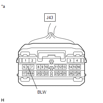
(a) Disconnect the J43 air conditioning amplifier assembly connector.
(b) Measure the resistance according to the value(s) in the table below.
Standard Resistance:
| Tester Connection | Condition | Specified Condition |
|---|---|---|
| J43-6 (BLW) - A16-2 (SI) | Always | Below 1 Ω |
| J43-6 (BLW) or A16-2 (SI) - Body ground | Always | 10 kΩ or higher |
| NG | | REPAIR OR REPLACE HARNESS OR CONNECTOR |
|
| 5. | INSPECT BLOWER MOTOR WITH FAN SUB-ASSEMBLY |
(a) Reconnect the A16 blower motor with fan sub-assembly connector.
| (b) Measure the voltage according to the value(s) in the table below. Standard Voltage:
|
|
| NG | | REPLACE BLOWER MOTOR WITH FAN SUB-ASSEMBLY |
|
| 6. | INSPECT AIR CONDITIONING AMPLIFIER ASSEMBLY |
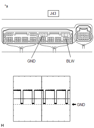
(a) Reconnect the J43 air conditioning amplifier assembly connector.
(b) Turn the engine switch on (IG).
(c) Turn the blower switch on (LO).
| (d) Measure the waveform between terminals J43-6 (BLW) and J43-4 (GND) of the air conditioning amplifier assembly. OK: Waveform is similar to that shown in the illustration. HINT: The waveform varies with the blower speed.
|
|
| OK | | REPLACE BLOWER MOTOR WITH FAN SUB-ASSEMBLY |
| NG | | REPLACE AIR CONDITIONING AMPLIFIER ASSEMBLY |
 Air Conditioning Control Panel Circuit
DESCRIPTION The radio receiver assembly (A/C control panel) switch signals are sent to the air conditioning amplifier assembly via CAN communication. WIRING DIAGRAM CAUTION / NOTICE / HINT NOTICE: In ...
 Air Conditioning Compressor Magnetic Clutch Circuit
DESCRIPTION When the air conditioning amplifier assembly is turned on, a magnetic clutch on signal is sent from the MGC terminal of the air conditioning amplifier assembly. Then, the semiconductor pwr ...
Other materials:
Lexus RX (RX 350L, RX450h) 2016-2026 Repair Manual > Meter / Gauge System: Meter Illumination does not Dim at Night
DESCRIPTION In this circuit, the combination meter assembly receives auto dimmer signals from the main body ECU (multiplex network body ECU) via CAN communication. When the combination meter assembly receives an auto dimmer signal, it dims the meter illumination (warning and indicator lights). The m ...
Lexus RX (RX 350L, RX450h) 2016-2026 Repair Manual > Audio And Visual System (for 12.3 Inch Display): "No GPS signal" mark is displayed
CAUTION / NOTICE / HINT NOTICE: Depending on the parts that are replaced during vehicle inspection or maintenance, performing initialization, registration or calibration may be needed. Refer to Precaution for Audio and Visual System. Click here PROCEDURE 1. CHECK CABIN (a) Check the cabin ...
Lexus RX (RX 350L, RX450h) 2016-{YEAR} Owners Manual
- For your information
- Pictorial index
- For safety and security
- Instrument cluster
- Operation of each component
- Driving
- Lexus Display Audio system
- Interior features
- Maintenance and care
- When trouble arises
- Vehicle specifications
- For owners
Lexus RX (RX 350L, RX450h) 2016-{YEAR} Repair Manual

0.0096