Lexus RX (RX 350L, RX450h) 2016-2026 Repair Manual: Air Conditioning Control Panel Circuit
DESCRIPTION
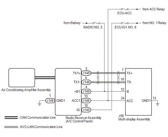
The radio receiver assembly (A/C control panel) switch signals are sent to the air conditioning amplifier assembly via CAN communication.
WIRING DIAGRAM
CAUTION / NOTICE / HINT
NOTICE:
Inspect the fuses for circuits related to this system before performing the following procedure.
PROCEDURE
| 1. | CHECK CAN COMMUNICATION SYSTEM |
(a) Using the Techstream, check if the CAN communication system is functioning normally.
Click here .gif)
| Result | Proceed to |
|---|---|
| CAN communication system DTCs are not output | A |
| CAN communication system DTCs are output | B |
| B | .gif) | GO TO CAN COMMUNICATION SYSTEM |
|
.gif)
| 2. | CHECK AVC-LAN COMMUNICATION CIRCUIT |
(a) Check for an open or short in all AVC-LAN communication circuits.
w/ Navigation System: Click here
w/ Audio and Visual System (for 12.3 Inch Display): Click here
w/ Audio and Visual System (for 8 Inch Display): Click here
OK:
There is no open or short circuit.
| NG | | REPAIR AVC-LAN COMMUNICATION CIRCUIT |
|
| 3. | CHECK HARNESS AND CONNECTOR (RADIO RECEIVER ASSEMBLY (A/C CONTROL PANEL) - POWER SOURCE AND BODY GROUND) |
(a) Disconnect the J148 and J149 radio receiver assembly (A/C control panel) connectors.
(b) Measure the voltage according to the value(s) in the table below.
Standard Voltage:
| Tester Connection | Condition | Specified Condition |
|---|---|---|
| J149-19 (IG) - Body ground | Engine switch on (IG) | 11 to 14 V |
| J148-15 (ACC1) - Body ground | Engine switch on (ACC) | 11 to 14 V |
| J148-4 (+B1) - Body ground | Always | 11 to 14 V |
(c) Measure the resistance according to the value(s) in the table below.
Standard Resistance:
| Tester Connection | Condition | Specified Condition |
|---|---|---|
| J148-1 (GND1) - Body ground | Always | Below 1 Ω |
| NG | | REPAIR OR REPLACE HARNESS OR CONNECTOR |
|
| 4. | CHECK HARNESS AND CONNECTOR (MULTI-DISPLAY ASSEMBLY - POWER SOURCE AND BODY GROUND) |
(a) Disconnect the J56 multi-display assembly connector.
(b) Measure the voltage according to the value(s) in the table below.
Standard Voltage:
| Tester Connection | Condition | Specified Condition |
|---|---|---|
| J56-24 (ACC) - Body ground | Engine switch on (ACC) | 11 to 14 V |
| J56-12 (B) - Body ground | Always | 11 to 14 V |
(c) Measure the resistance according to the value(s) in the table below.
Standard Resistance:
| Tester Connection | Condition | Specified Condition |
|---|---|---|
| J56-13 (GND1) - Body ground | Always | Below 1 Ω |
| OK | | PROCEED TO NEXT SUSPECTED AREA SHOWN IN PROBLEM SYMPTOMS TABLE |
| NG | | REPAIR OR REPLACE HARNESS OR CONNECTOR |
 Lost Communication with ECM (U0100-U0142,U0151,U0155,U0163)
DESCRIPTION DTC No. Detection Item DTC Detection Condition Trouble Area Memory U0100 Lost Communication with ECM No communication with ECM
CAN communication system
ECM
M ...
 Blower Motor Circuit
DESCRIPTION The blower motor with fan sub-assembly is operated by signals from the air conditioning amplifier assembly. Blower motor speed signals are transmitted in accordance with changes in the dut ...
Other materials:
Lexus RX (RX 350L, RX450h) 2016-2026 Repair Manual > Power Tilt And Power Telescopic Steering Column System: Data List / Active Test
DATA LIST / ACTIVE TEST READ DATA LIST HINT: Using the Techstream to read the Data List allows the values or states of switches, sensors, actuators and other items to be read without removing any parts. This non-intrusive inspection can be very useful because intermittent conditions or signals may b ...
Lexus RX (RX 350L, RX450h) 2016-2026 Repair Manual > Sfi System: Freeze Frame Data
FREEZE FRAME DATA DESCRIPTION The ECM records vehicle and driving condition information as freeze frame data the moment a DTC is stored. When troubleshooting, freeze frame data can be helpful in determining whether the vehicle was moving or stationary, whether the engine was warmed up or not, whethe ...
Lexus RX (RX 350L, RX450h) 2016-{YEAR} Owners Manual
- For your information
- Pictorial index
- For safety and security
- Instrument cluster
- Operation of each component
- Driving
- Lexus Display Audio system
- Interior features
- Maintenance and care
- When trouble arises
- Vehicle specifications
- For owners
Lexus RX (RX 350L, RX450h) 2016-{YEAR} Repair Manual

0.011