Lexus RX (RX 350L, RX450h) 2016-2026 Repair Manual: Exhaust Gas Sensor Circuit (B1418/18)
DESCRIPTION
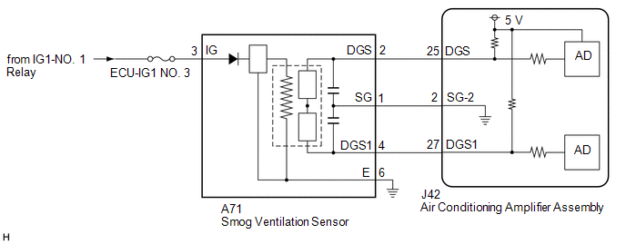
The smog ventilation sensor is installed to the front of the cooler condenser assembly to automatically control the air inlet mode (fresh, recirculation/fresh, and recirculation).
This sensor detects HC and CO in the ambient air and transmits signals to the air conditioning amplifier assembly.
| DTC No. | Detection Item | DTC Detection Condition | Trouble Area | Memory |
|---|---|---|---|---|
| B1418/18 | Exhaust Gas Sensor Circuit | Open or short in smog ventilation sensor circuit (HC, CO) (w/ Smog Ventilation Sensor) |
| - |
WIRING DIAGRAM
CAUTION / NOTICE / HINT
NOTICE:
- Inspect the fuses for circuits related to this system before performing the following procedure.
- If DTCs B1418/18 and B1461/61 are stored simultaneously, there may be a malfunction in the smog ventilation sensor power source circuit.
PROCEDURE
| 1. | READ VALUE USING TECHSTREAM |
(a) Connect the Techstream to the DLC3.
(b) Turn the engine switch on (IG).
(c) Turn the Techstream on.
(d) Allow exhaust gas (HC, CO) to travel to the sensing portion of the smog ventilation sensor.
(e) Enter the following menus: Body Electrical / Air Conditioner / Data List.
(f) Read the Data List according to the display on the Techstream.
Body Electrical > Air Conditioner > Data List| Tester Display | Measurement Item | Range | Normal Condition | Diagnostic Note |
|---|---|---|---|---|
| Emission Gas Sensor | Emission gas (HC, CO) | Min.: 0 Max.: 255 | Smog ventilation sensor value increases as gas amount increases | - |
| Tester Display |
|---|
| Emission Gas Sensor |
OK:
The display is as specified in the normal condition column.
| Result | Proceed to |
|---|---|
| NG | A |
| OK (When troubleshooting according to Problem Symptoms Table) | B |
| OK (When troubleshooting according to the DTC) | C |
| B | .gif) | PROCEED TO NEXT SUSPECTED AREA SHOWN IN PROBLEM SYMPTOMS TABLE |
.gif)
| C | | REPLACE AIR CONDITIONING AMPLIFIER ASSEMBLY |
|
.gif)
| 2. | CHECK HARNESS AND CONNECTOR (SMOG VENTILATION SENSOR - IG POWER SOURCE AND BODY GROUND) |
(a) Disconnect the A71 smog ventilation sensor connector.
(b) Measure the voltage according to the value(s) in the table below.
Standard Voltage:
| Tester Connection | Condition | Specified Condition |
|---|---|---|
| A71-3 (IG) - Body ground | Engine switch on (IG) | 11 to 14 V |
| A71-3 (IG) - Body ground | Engine switch off | Below 1 V |
(c) Measure the resistance according to the value(s) in the table below.
Standard Resistance:
| Tester Connection | Condition | Specified Condition |
|---|---|---|
| A71-6 (E) - Body ground | Always | Below 1 Ω |
| NG | | REPAIR OR REPLACE HARNESS OR CONNECTOR |
|
| 3. | CHECK HARNESS AND CONNECTOR (SMOG VENTILATION SENSOR - AIR CONDITIONING AMPLIFIER ASSEMBLY) |
(a) Disconnect the J42 air conditioning amplifier assembly connector.
(b) Measure the resistance according to the value(s) in the table below.
Standard Resistance:
| Tester Connection | Condition | Specified Condition |
|---|---|---|
| A71-1 (SG) - J42-2 (SG-2) | Always | Below 1 Ω |
| A71-2 (DGS) - J42-25 (DGS) | Always | Below 1 Ω |
| J42-2 (SG-2) or A71-1 (SG) - Body ground | Always | 10 kΩ or higher |
| J42-25 (DGS) or A71-2 (DGS) - Body ground | Always | 10 kΩ or higher |
| NG | | REPAIR OR REPLACE HARNESS OR CONNECTOR |
|
| 4. | INSPECT SMOG VENTILATION SENSOR |
| (a) Remove the smog ventilation sensor. Click here |
|
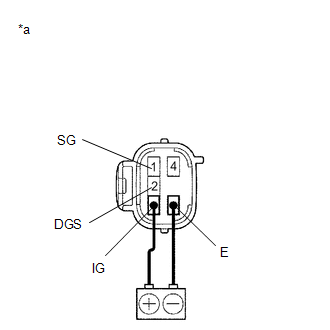
(b) Connect a positive (+) lead from the battery to terminal 3 (IG) and a negative (-) lead to terminal 6 (E).
(c) Allow exhaust gas (HC, CO) to travel to the sensing portion of the smog ventilation sensor, and measure the resistance between terminals 1 (SG) and 2 (DGS).
OK:
When the sensor is exposed to exhaust gas, the resistance increases.
HINT:
The resistance of the sensor before being exposed to exhaust gas is 10 kΩ to 40 kΩ.
| OK | | REPLACE AIR CONDITIONING AMPLIFIER ASSEMBLY |
| NG | | REPLACE SMOG VENTILATION SENSOR |
 Evaporator Temperature Circuit (B1417/17)
DESCRIPTION The No. 2 air conditioning harness assembly is installed on the evaporator in the rear air conditioner unit to detect the temperature of the cooled air that has passed through the evaporat ...
 Rear Room Temperature Sensor Circuit (B1419/19)
DESCRIPTION The cooler (No. 2 room temp. sensor) thermistor is installed in the rear panel to detect the rear cabin temperature, which is used to control the air conditioning system. The resistance of ...
Other materials:
Lexus RX (RX 350L, RX450h) 2016-2026 Repair Manual > Oil Pressure Switch: Inspection
INSPECTION PROCEDURE 1. INSPECT ENGINE OIL PRESSURE SWITCH ASSEMBLY (a) Disconnect the wire harness protector. *1 Wire Harness Protector (b) Disconnect the engine oil pressure switch assembly connector. (c) Start the engine. (d) Measure the resistance according to the v ...
Lexus RX (RX 350L, RX450h) 2016-2026 Repair Manual > Rear Power Seat Control System(for Second Row): Park / Neutral Position Switch Circuit
DESCRIPTION The fold seat control ECU receives switch operation signals, the back door courtesy light switch assembly signal*1, rear door courtesy light switch assembly signal*2 and driving condition signal and operates the rear power seat according these signals.
*1: When using fold seat switch ...
Lexus RX (RX 350L, RX450h) 2016-{YEAR} Owners Manual
- For your information
- Pictorial index
- For safety and security
- Instrument cluster
- Operation of each component
- Driving
- Lexus Display Audio system
- Interior features
- Maintenance and care
- When trouble arises
- Vehicle specifications
- For owners
Lexus RX (RX 350L, RX450h) 2016-{YEAR} Repair Manual

0.0096