Lexus RX (RX 350L, RX450h) 2016-2026 Repair Manual: Removal
REMOVAL
CAUTION / NOTICE / HINT
The necessary procedures (adjustment, calibration, initialization or registration) that must be performed after parts are removed and installed, or replaced during front door window frame moulding removal/installation are shown below.
Necessary Procedures After Parts Removed/Installed/Replaced| Replaced Part or Performed Procedure | Necessary Procedure | Effect/Inoperative Function when Necessary Procedure not Performed | Link |
|---|---|---|---|
|
*1: When performing learning using the Techstream.
Click here | |||
| Disconnect cable from negative (-) battery terminal | Memorize steering angle neutral point | Lane Control System | |
| Pre-collision System | |||
| Intelligent Clearance Sonar System*1 | |||
| Parking Assist Monitor System | | ||
| Panoramic View Monitor System | | ||
| Lighting System (w/ Automatic Headlight Beam Level Control System) | | ||
| Initialize back door lock | Power Door Lock Control System | | |
| Reset back door close position | Power Back Door System (w/ Outside Door Control Switch) | | |
HINT:
- Use the same procedure for the RH side and LH side.
- The following procedure is for the LH side.
PROCEDURE
1. REMOVE FRONT DOOR BELT MOULDING ASSEMBLY
Click here .gif)
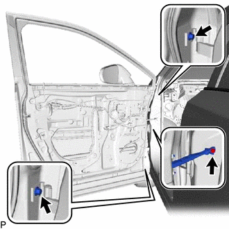
2. DISCONNECT FRONT DOOR WEATHERSTRIP
| (a) Disengage the 9 clips and disconnect the front door weatherstrip. |
|
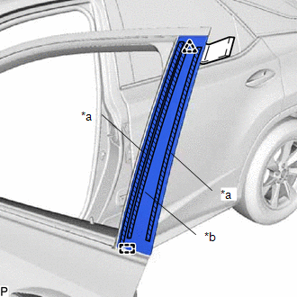
3. REMOVE FRONT DOOR REAR WINDOW FRAME MOULDING
HINT:
When removing the front door rear window frame moulding, heat the vehicle body and front door rear window frame moulding using a heat light.
Heating Temperature| Item | Temperature |
|---|---|
| Vehicle Body | 40 to 60°C (104 to 140°F) |
| Front Door Rear Window Frame Moulding | 20 to 30°C (68 to 86°F) |
CAUTION:
- Do not touch the heat light and heated parts, touching the heat light may result in burns.
- Touching heated parts for a long time may result in burns.
.png)
| *a | Heated Part |
| *b | Heat Light |
NOTICE:
Do not heat the vehicle body or moulding excessively.
(a) Using a heat light, heat the front door rear window frame moulding.
| (b) Using a moulding remover, disengage the clip and guide, and separate the double-sided tape and caulking sponge to remove the front door rear window frame moulding. |
|
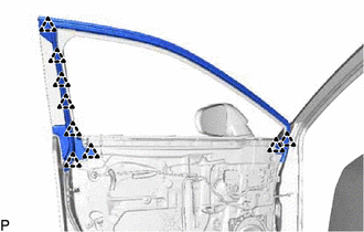
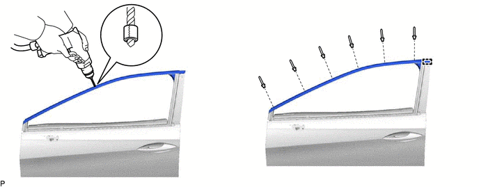
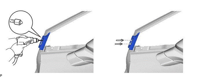
4. REMOVE FRONT DOOR UPPER WINDOW FRAME MOULDING
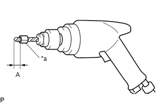
(a) Insert a 4.0 mm (0.157 in.) drill bit into a drill.
| (b) Tape the 4.0 mm (0.157 in.) drill bit 5.0 mm (0.197 in.) from the tip as shown in the illustration. Standard Measurement:
NOTICE: Tape the 4.0 mm (0.157 in.) drill bit to prevent the drill bit from going too deep. |
|
(c) Lightly press the drill against the rivets to drill off the rivet flanges, and remove the 6 rivets.
CAUTION:
Be careful of the drilled rivets, as they may be hot.
NOTICE:
- Pressing the drill too firmly will cause the rivet to turn and result in the rivet not being drilled through.
- Prying the rivets with the drill may damage the rivet installation holes or drill bit.
(d) Using a vacuum cleaner, remove the rivet fragments and shavings from the drilled areas.
(e) Disengage the guide and remove the front door upper window frame moulding from the door frame.
5. REMOVE FRONT DOOR SCUFF PLATE
w/o Rear No. 2 Seat: Click here
w/ Rear No. 2 Seat: Click here
6. REMOVE COWL SIDE TRIM BOARD
Click here
7. REMOVE FRONT DOOR FRONT WINDOW FRAME MOULDING
(a) Disconnect each connector.
(b) Disengage each clamp.
| (c) Remove the 3 bolts and front door panel sub-assembly. NOTICE: To prevent damage, when removing the front door panel sub-assembly, make sure that there are enough people available to hold it securely. |
|
(d) Insert a 4.0 mm (0.157 in.) drill bit into a drill.
| (e) Tape the 4.0 mm (0.157 in.) drill bit 5.0 mm (0.197 in.) from the tip as shown in the illustration. Standard Measurement:
NOTICE: Tape the 4.0 mm (0.157 in.) drill bit to prevent the drill bit from going too deep. |
|
(f) Lightly press the drill against the rivets to drill off the rivet flanges, and remove the 2 rivets and front door front window frame moulding.
CAUTION:
Be careful of the drilled rivets, as they may be hot.
NOTICE:
- Pressing the drill too firmly will cause the rivet to turn and result in the rivet not being drilled through.
- Prying the rivets with the drill may damage the rivet installation holes or drill bit.
 Installation
INSTALLATION CAUTION / NOTICE / HINT HINT:
Use the same procedure for the RH side and LH side.
The following procedure is for the LH side.
PROCEDURE 1. INSTALL FRONT DOOR FRONT WINDOW FRAME MO ...
 Name Plate
...
Other materials:
Lexus RX (RX 350L, RX450h) 2016-2026 Repair Manual > Washer Nozzle(for Front Side): On-vehicle Inspection
ON-VEHICLE INSPECTION PROCEDURE 1. INSPECT WASHER NOZZLE SUB-ASSEMBLY (a) Operate the washer nozzle sub-assemblies and check the position that the washer fluid contacts the windshield. Standard: Center of washer fluid contacts the windshield in the areas shown in the illustration. *a Upper Li ...
Lexus RX (RX 350L, RX450h) 2016-2026 Repair Manual > Power Back Door System (w/ Outside Door Control Switch): Lock Function does not Operate (Close &)
DESCRIPTION The door control switch signal is sent to the multiplex network door ECU. If the power back door system does not operate when the door control switch is operated, the door control switch circuit may be malfunctioning. WIRING DIAGRAM CAUTION / NOTICE / HINT NOTICE:
If the replacement, ...
Lexus RX (RX 350L, RX450h) 2016-{YEAR} Owners Manual
- For your information
- Pictorial index
- For safety and security
- Instrument cluster
- Operation of each component
- Driving
- Lexus Display Audio system
- Interior features
- Maintenance and care
- When trouble arises
- Vehicle specifications
- For owners
Lexus RX (RX 350L, RX450h) 2016-{YEAR} Repair Manual

0.0098