Lexus RX (RX 350L, RX450h) 2016-2026 Repair Manual: Removal
REMOVAL
CAUTION / NOTICE / HINT
The necessary procedures (adjustment, calibration, initialization or registration) that must be performed after parts are removed and installed, or replaced during cruise control main switch removal/installation are shown below.
Necessary Procedures After Parts Removed/Installed/Replaced| Replaced Part or Performed Procedure | Necessary Procedure | Effect/Inoperative Function when Necessary Procedure not Performed | Link |
|---|---|---|---|
| Disconnect cable from negative battery terminal | Memorize steering angle neutral point | Lane Control System | |
| Intelligent Clearance Sonar System*1 | |||
| Pre-collision System | |||
| Lighting System (w/ Automatic Headlight Beam Level Control System) | | ||
| Parking Assist Monitor System | | ||
| Panoramic View Monitor System | | ||
| Initialize back door lock | Power Door Lock Control System | | |
| Reset back door close position | Power Back Door System (w/ Outside Door Control Switch) | |
*1: When performing learning using the Techstream.
Click here .gif)
CAUTION:
Some of these service operations affect the SRS airbag system. Read the precautionary notices concerning the SRS airbag system before servicing.
Click here
PROCEDURE
1. REMOVE HORN BUTTON ASSEMBLY
Click here
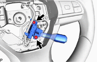
2. REMOVE CRUISE CONTROL MAIN SWITCH
| (a) Remove the 2 screws. |
|
(b) Pull the cruise control main switch as shown in the illustration.
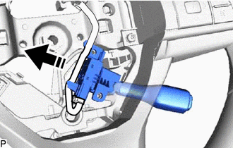
.png) | Remove in this Direction |
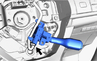
| (c) Disconnect the connector to remove the cruise control main switch. |
|
 Components
COMPONENTS ILLUSTRATION *1 CRUISE CONTROL MAIN SWITCH *2 HORN BUTTON ASSEMBLY N*m (kgf*cm, ft.*lbf): Specified torque - - ...
 Inspection
INSPECTION PROCEDURE 1. INSPECT CRUISE CONTROL MAIN SWITCH (a) Measure the resistance according to the value(s) in the table below. *a Component without harness connected (Cruise Control Switch) ...
Other materials:
Lexus RX (RX 350L, RX450h) 2016-2026 Repair Manual > Front Bumper: Removal
REMOVAL CAUTION / NOTICE / HINT The necessary procedures (adjustment, calibration, initialization, or registration) that must be performed after parts are removed and installed, or replaced during front bumper assembly removal/installation are shown below. Necessary Procedures After Parts Removed/In ...
Lexus RX (RX 350L, RX450h) 2016-2026 Repair Manual > Occupant Classification System: System Description
SYSTEM DESCRIPTION GENERAL (a) The occupant detection ECU estimates the weight of an occupant based on signals received from the 2 occupant classification sensors. The occupant detection ECU determines whether the front passenger seat is occupied and classifies the occupant based on the estimated we ...
Lexus RX (RX 350L, RX450h) 2016-{YEAR} Owners Manual
- For your information
- Pictorial index
- For safety and security
- Instrument cluster
- Operation of each component
- Driving
- Lexus Display Audio system
- Interior features
- Maintenance and care
- When trouble arises
- Vehicle specifications
- For owners
Lexus RX (RX 350L, RX450h) 2016-{YEAR} Repair Manual

0.0098