Lexus RX (RX 350L, RX450h) 2016-2026 Repair Manual: Brake Switch "A" Signal Compare Failure (P057162)
DESCRIPTION
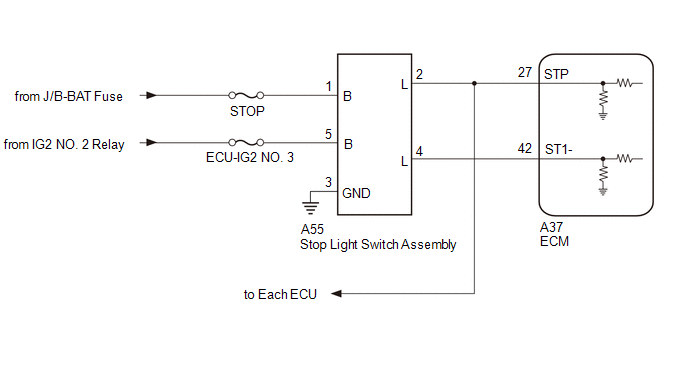
When the brake pedal is depressed, the stop light switch assembly outputs a signal to the ECM. The ECM uses this signal to control cancellation of vehicle speed by the dynamic radar cruise control. When the ECM determines that terminals STP and ST1 of the stop light switch assembly are both less than 1 V, DTC P057162 is stored.
| DTC No. | Detection Item | DTC Detection Condition | Trouble Area | MIL | DTC Output from |
|---|---|---|---|---|---|
| P057162 | Brake Switch "A" Signal Compare Failure | When the engine switch is on (IG) and the dynamic radar cruise control system is operating, the ECM detects that the voltage at terminal STP and ST1- are both less than 1 V for approximately 0.5 seconds or more. |
| Does not come on | Cruise Control |
WIRING DIAGRAM
CAUTION / NOTICE / HINT
NOTICE:
- Inspect the fuses for circuits related to this system before performing the following procedure.
-
Before replacing the ECM, refer to Registration.
Click here
.gif)
PROCEDURE
| 1. | CHECK HARNESS AND CONNECTOR (STOP LIGHT SWITCH ASSEMBLY - BATTERY AND BODY GROUND) |
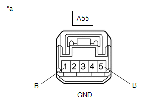
| (a) Disconnect the A55 stop light switch assembly connector. |
|
(b) Measure the resistance according to the value(s) in the table below.
Standard Resistance:
| Tester Connection | Condition | Specified Condition |
|---|---|---|
| A55-3 (GND) - Body ground | Always | Below 1 Ω |
(c) Measure the voltage according to the value(s) in the table below.
Standard Voltage:
| Tester Connection | Condition | Specified Condition |
|---|---|---|
| A55-1 (B) - Body ground | Always | 11 to 14 V |
| A55-5 (B) - Body ground | Engine switch on (IG) | 11 to 14 V |
| A55-5 (B) - Body ground | Engine switch off | Below 1 V |
| NG | .gif) | REPAIR OR REPLACE HARNESS OR CONNECTOR |
|
.gif)
| 2. | INSPECT STOP LIGHT SWITCH ASSEMBLY |
(a) Inspect the stop light switch assembly.
Click here
| NG | | REPLACE STOP LIGHT SWITCH ASSEMBLY |
|
| 3. | CHECK HARNESS AND CONNECTOR (STOP LIGHT SWITCH ASSEMBLY - ECM) |
(a) Disconnect the A55 stop light switch assembly connector.
(b) Disconnect the A37 ECM connector.
(c) Disconnect each ECU connector.
(d) Measure the resistance according to the value(s) in the table below.
Standard Resistance:
| Tester Connection | Condition | Specified Condition |
|---|---|---|
| A55-2 (L) - A37-27 (STP) | Always | Below 1 Ω |
| A55-4 (L) - A37-42 (ST1-) | Always | Below 1 Ω |
| A55-2 (L) or A37-27 (STP) - Body ground | Always | 10 kΩ or higher |
| A55-4 (L) or A37-42 (ST1-) - Body ground | Always | 10 kΩ or higher |
| OK | | REPLACE ECM |
| NG | | REPAIR OR REPLACE HARNESS OR CONNECTOR |
 Brake Switch "A" Circuit Open (P057113)
DESCRIPTION When the brakes are applied by the dynamic radar cruise control system, the skid control ECU (brake actuator assembly) operates the stop light switch assembly (stop light control relay) to ...
 Cruise Control System Internal Failure (P057504,P057549)
DESCRIPTION When the ECM detects an internal malfunction, DTC P057504 or P057549 is stored. DTC No. Detection Item DTC Detection Condition Trouble Area MIL DTC Output from P057504 C ...
Other materials:
Lexus RX (RX 350L, RX450h) 2016-2026 Repair Manual > Wireless Charging System: Precaution
PRECAUTION PRECAUTION FOR DISCONNECTING CABLE FROM NEGATIVE BATTERY TERMINAL NOTICE: When disconnecting the cable from the negative (-) battery terminal, initialize the following systems after the terminal is reconnected. System Name See Procedure Lane Control System Pre-collision ...
Lexus RX (RX 350L, RX450h) 2016-2026 Repair Manual > Audio And Visual System (for 8 Inch Display): Sound Signal Circuit between Radio Receiver and Stereo Jack Adapter
DESCRIPTION The No. 1 stereo jack adapter assembly sends the sound signal from an external device to the radio receiver assembly via this circuit. WIRING DIAGRAM PROCEDURE 1. CHECK HARNESS AND CONNECTOR (RADIO RECEIVER ASSEMBLY - NO. 1 STEREO JACK ADAPTER ASSEMBLY) (a) Disconnect the J148 ...
Lexus RX (RX 350L, RX450h) 2016-{YEAR} Owners Manual
- For your information
- Pictorial index
- For safety and security
- Instrument cluster
- Operation of each component
- Driving
- Lexus Display Audio system
- Interior features
- Maintenance and care
- When trouble arises
- Vehicle specifications
- For owners
Lexus RX (RX 350L, RX450h) 2016-{YEAR} Repair Manual

0.0131