Lexus RX (RX 350L, RX450h) 2016-2026 Repair Manual: Parts Location
PARTS LOCATION
ILLUSTRATION
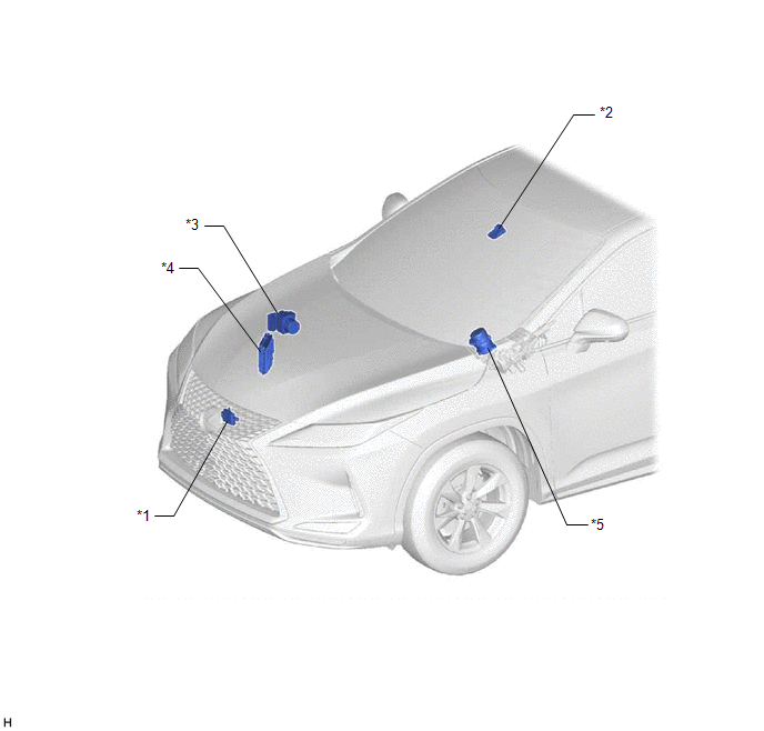
| *1 | MILLIMETER WAVE RADAR SENSOR ASSEMBLY | *2 | FORWARD RECOGNITION CAMERA |
| *3 | SKID CONTROL ECU (BRAKE ACTUATOR ASSEMBLY) | *4 | ECM |
| *5 | POWER STEERING ECU ASSEMBLY | - | - |
ILLUSTRATION
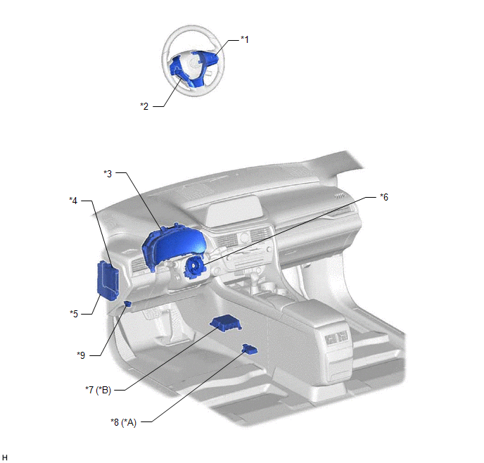
| *A | for TFT Meter Type | *B | for Optitron Meter Type |
| *1 | STEERING PAD SWITCH ASSEMBLY - LTA MAIN SWITCH | *2 | STEERING VIBRATION ECU |
| *3 | COMBINATION METER ASSEMBLY | *4 | MAIN BODY ECU (MULTIPLEX NETWORK BODY ECU) |
| *5 | INSTRUMENT PANEL JUNCTION BLOCK ASSEMBLY - ECU-IG1 NO. 2 FUSE | *6 | SPIRAL CABLE WITH SENSOR SUB-ASSEMBLY - SPIRAL CABLE SUB-ASSEMBLY - STEERING SENSOR |
| *7 | AIRBAG SENSOR ASSEMBLY | *8 | YAW RATE SENSOR ASSEMBLY |
| *9 | DLC3 | - | - |
 Precaution
PRECAUTION PRECAUTION FOR DISCONNECTING CABLE FROM NEGATIVE BATTERY TERMINAL NOTICE:
When disconnecting the cable from the negative (-) battery terminal, initialize the following systems after the ...
 System Diagram
SYSTEM DIAGRAM LOCAL BUS ...
Other materials:
Lexus RX (RX 350L, RX450h) 2016-2026 Repair Manual > 2gr-fks (starting): Starting System
Parts LocationPARTS LOCATION ILLUSTRATION *1 STARTER ASSEMBLY *2 ECM *3 ENGINE ROOM RELAY BLOCK ASSEMBLY - ST RELAY - ST NO. 1 FUSE *4 PARK/NEUTRAL POSITION SWITCH ASSEMBLY ILLUSTRATION *1 ENGINE SWITCH *2 CERTIFICATION ECU (SMART KEY ECU ASSEMBLY) System DiagramS ...
Lexus RX (RX 350L, RX450h) 2016-2026 Repair Manual > Front Seat Side Airbag Assembly: Installation
INSTALLATION CAUTION / NOTICE / HINT HINT:
Use the same procedure for the RH side and LH side.
The following procedure is for the LH side.
PROCEDURE 1. INSTALL FRONT SEAT AIRBAG ASSEMBLY (a) Install the front seat airbag assembly with 2 new nuts. Torque: 5.5 N·m {56 kgf·cm, 49 in·lbf} N ...
Lexus RX (RX 350L, RX450h) 2016-{YEAR} Owners Manual
- For your information
- Pictorial index
- For safety and security
- Instrument cluster
- Operation of each component
- Driving
- Lexus Display Audio system
- Interior features
- Maintenance and care
- When trouble arises
- Vehicle specifications
- For owners
Lexus RX (RX 350L, RX450h) 2016-{YEAR} Repair Manual

0.0109