Lexus RX (RX 350L, RX450h) 2016-2026 Repair Manual: Radio Receiver Assembly Communication Stop Mode
DESCRIPTION
| Detection Item | Symptom | Trouble Area |
|---|---|---|
| Radio Receiver Assembly Communication Stop Mode | Either condition is met:
|
|
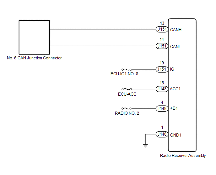
WIRING DIAGRAM
CAUTION / NOTICE / HINT
CAUTION:
When performing the confirmation driving pattern, obey all speed limits and traffic laws.
NOTICE:
- Before measuring the resistance of the CAN bus, turn the engine switch off and leave the vehicle for 1 minute or more without operating the key or any switches, or opening or closing the doors. After that, disconnect the cable from the negative (-) battery terminal and leave the vehicle for 1 minute or more before measuring the resistance.
-
After turning the engine switch off, waiting time may be required before disconnecting the cable from the negative (-) battery terminal. Therefore, make sure to read the disconnecting the cable from the negative (-) battery terminal notices before proceeding with work.
Click here
.gif)
-
Because the order of diagnosis is important to allow correct diagnosis, make sure to begin troubleshooting using How to Proceed with Troubleshooting when CAN communication system related DTCs are output.
Click here
-
After performing repairs, perform the DTC check procedure and confirm that the DTCs are not output again.
DTC check procedure: Turn the engine switch on (IG) and wait for 1 minute or more. Then operate the suspected malfunctioning system and drive the vehicle at 60 km/h (37 mph) or more for 5 minutes or more.
-
After the repair, perform the CAN bus check and check that all the ECUs and sensors connected to the CAN communication system are displayed.
Click here
- Inspect the fuses for circuits related to this system before performing the following procedure.
HINT:
- Operating the engine switch, any other switches or a door triggers related ECU and sensor communication on the CAN. This communication will cause the resistance value to change.
- Even after DTCs are cleared, if a DTC is stored again after driving the vehicle for a while, the malfunction may be occurring due to vibration of the vehicle. In such a case, wiggling the ECUs or wire harness while performing the inspection below may help determine the cause of the malfunction.
PROCEDURE
| 1. | CHECK FOR OPEN IN CAN BUS LINES (RADIO RECEIVER ASSEMBLY BRANCH LINE) |
(a) Disconnect the cable from the negative (-) battery terminal.
| (b) Disconnect the J151 radio receiver assembly connector. |
|
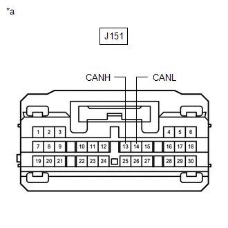
(c) Measure the resistance according to the value(s) in the table below.
Standard Resistance:
| Tester Connection | Condition | Specified Condition |
|---|---|---|
| J151-13 (CANH) - J151-14 (CANL) | Cable disconnected from negative (-) battery terminal | 54 to 69 Ω |
| NG | .gif) | REPAIR OR REPLACE CAN BRANCH LINES OR CONNECTOR (RADIO RECEIVER ASSEMBLY) |
|
.gif)
| 2. | CHECK HARNESS AND CONNECTOR (POWER SOURCE CIRCUIT) |
(a) Disconnect the J148 radio receiver assembly connector.
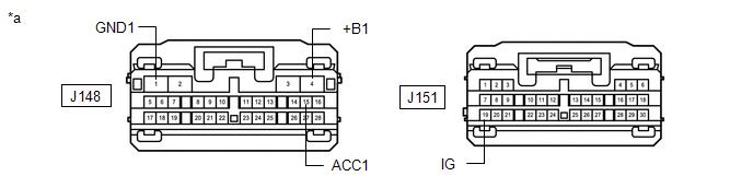
| *a | Front view of wire harness connector (to Radio Receiver Assembly) | - | - |
(b) Measure the resistance according to the value(s) in the table below.
Standard Resistance:
| Tester Connection | Condition | Specified Condition |
|---|---|---|
| J148-1 (GND1) - Body ground | Cable disconnected from negative (-) battery terminal | Below 1 Ω |
(c) Reconnect the cable to the negative (-) battery terminal.
(d) Measure the voltage according to the value(s) in the table below.
Standard Voltage:
| Tester Connection | Condition | Specified Condition |
|---|---|---|
| J148-4 (+B1) - Body ground | Always | 11 to 14 V |
| J148-15 (ACC1) - Body ground | Engine switch on (ACC) | 11 to 14 V |
| J151-19 (IG) - Body ground | Engine switch on (IG) | 11 to 14 V |
| OK | | REPLACE RADIO RECEIVER ASSEMBLY |
| NG | | REPAIR OR REPLACE HARNESS OR CONNECTOR (POWER SOURCE CIRCUIT) |
 4WD Control ECU Communication Stop Mode
DESCRIPTION Detection Item Symptom Trouble Area 4WD Control ECU Communication Stop Mode Either condition is met:
"Four Wheel Drive Control" is not displayed on the CAN Bus Check screen ...
 Blind Spot Monitor Sensor Communication Stop Mode
DESCRIPTION Detection Item Symptom Trouble Area Blind Spot Monitor Sensor Communication Stop Mode Either condition is met:
"Blind Spot Monitor Master" is not displayed on the CAN Bus C ...
Other materials:
Lexus RX (RX 350L, RX450h) 2016-2026 Repair Manual > Glove Box Light: Components
COMPONENTS ILLUSTRATION *1 COWL SIDE TRIM BOARD RH *2 FRONT DOOR SCUFF PLATE RH *3 GLOVE BOX LIGHT ASSEMBLY *4 GLOVE COMPARTMENT DOOR ASSEMBLY *5 INSTRUMENT PANEL GARNISH RH *6 LOWER NO. 1 INSTRUMENT PANEL FINISH PANEL *7 NO. 2 INSTRUMENT PANEL UNDER COVER SUB-ASS ...
Lexus RX (RX 350L, RX450h) 2016-2026 Repair Manual > Sfi System: Actuator Supply Voltage "A" Stuck On (P06579E)
MONITOR DESCRIPTION The ECM monitors the output voltage to the throttle actuator. This self-check ensures that the ECM is functioning properly. The output voltage is usually 0 V when the engine switch is turned off. If the output voltage is 7 V or higher when the engine switch is turned off, the ECM ...
Lexus RX (RX 350L, RX450h) 2016-{YEAR} Owners Manual
- For your information
- Pictorial index
- For safety and security
- Instrument cluster
- Operation of each component
- Driving
- Lexus Display Audio system
- Interior features
- Maintenance and care
- When trouble arises
- Vehicle specifications
- For owners
Lexus RX (RX 350L, RX450h) 2016-{YEAR} Repair Manual

0.012