Lexus RX (RX 350L, RX450h) 2016-2026 Repair Manual: Parking Assist ECU Communication Stop Mode
DESCRIPTION
| Detection Item | Symptom | Trouble Area |
|---|---|---|
| Parking Assist ECU Communication Stop Mode | Either condition is met:
|
|
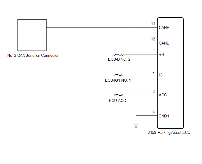
WIRING DIAGRAM
CAUTION / NOTICE / HINT
CAUTION:
When performing the confirmation driving pattern, obey all speed limits and traffic laws.
NOTICE:
- Before measuring the resistance of the CAN bus, turn the engine switch off and leave the vehicle for 1 minute or more without operating the key or any switches, or opening or closing the doors. After that, disconnect the cable from the negative (-) battery terminal and leave the vehicle for 1 minute or more before measuring the resistance.
-
After turning the engine switch off, waiting time may be required before disconnecting the cable from the negative (-) battery terminal. Therefore, make sure to read the disconnecting the cable from the negative (-) battery terminal notices before proceeding with work.
Click here
.gif)
-
Because the order of diagnosis is important to allow correct diagnosis, make sure to begin troubleshooting using How to Proceed with Troubleshooting when CAN communication system related DTCs are output.
Click here
-
After performing repairs, perform the DTC check procedure and confirm that the DTCs are not output again.
DTC check procedure: Turn the engine switch on (IG) and wait for 1 minute or more. Then operate the suspected malfunctioning system and drive the vehicle at 60 km/h (37 mph) or more for 5 minutes or more.
-
After the repair, perform the CAN bus check and check that all the ECUs and sensors connected to the CAN communication system are displayed.
Click here
- Inspect the fuses for circuits related to this system before performing the following procedure.
HINT:
- Operating the engine switch, any other switches or a door triggers related ECU and sensor communication on the CAN. This communication will cause the resistance value to change.
- Even after DTCs are cleared, if a DTC is stored again after driving the vehicle for a while, the malfunction may be occurring due to vibration of the vehicle. In such a case, wiggling the ECUs or wire harness while performing the inspection below may help determine the cause of the malfunction.
PROCEDURE
| 1. | CHECK FOR OPEN IN CAN BUS LINES (PARKING ASSIST ECU BRANCH LINE) |
(a) Disconnect the cable from the negative (-) battery terminal.
| (b) Disconnect the J159 parking assist ECU connector. |
|
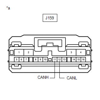
(c) Measure the resistance according to the value(s) in the table below.
Standard Resistance:
| Tester Connection | Condition | Specified Condition |
|---|---|---|
| J159-11 (CANH) - J159-12 (CANL) | Cable disconnected from negative (-) battery terminal | 54 to 69 Ω |
| NG | .gif) | REPAIR OR REPLACE CAN BRANCH LINES OR CONNECTOR (PARKING ASSIST ECU) |
|
.gif)
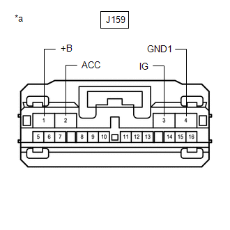
| 2. | CHECK HARNESS AND CONNECTOR (POWER SOURCE CIRCUIT) |
| (a) Measure the resistance according to the value(s) in the table below. Standard Resistance:
|
|
(b) Reconnect the cable to the negative (-) battery terminal.
(c) Measure the voltage according to the value(s) in the table below.
Standard Voltage:
| Tester Connection | Condition | Specified Condition |
|---|---|---|
| J159-1 (+B) - Body ground | Always | 11 to 14 V |
| J159-2 (ACC) - Body ground | Engine switch on (ACC) | 11 to 14 V |
| J159-3 (IG) - Body ground | Engine switch on (IG) | 11 to 14 V |
| OK | | REPLACE PARKING ASSIST ECU |
| NG | | REPAIR OR REPLACE HARNESS OR CONNECTOR (POWER SOURCE CIRCUIT) |
 Blind Spot Monitor Sensor Communication Stop Mode
DESCRIPTION Detection Item Symptom Trouble Area Blind Spot Monitor Sensor Communication Stop Mode Either condition is met:
"Blind Spot Monitor Master" is not displayed on the CAN Bus C ...
 DCM Communication Stop Mode
DESCRIPTION Detection Item Symptom Trouble Area DCM Communication Stop Mode Either condition is met:
"DCM" is not displayed on the CAN Bus Check screen of the Techstream.
Click here ...
Other materials:
Lexus RX (RX 350L, RX450h) 2016-2026 Repair Manual > Sfi System: Camshaft Position "A" - Timing Over-Advanced or System Performance Bank 1 (P001100,P001200,P002100,P002200)
DESCRIPTION Refer to DTC P001013. Click here DTC No. Detection Item DTC Detection Condition Trouble Area MIL Memory Note P001100 Camshaft Position "A" - Timing Over-Advanced or System Performance Bank 1 Intake valve timing is stuck at a certain value when in the advance rang ...
Lexus RX (RX 350L, RX450h) 2016-2026 Repair Manual > Thermostat: Installation
INSTALLATION PROCEDURE 1. INSTALL WATER INLET WITH THERMOSTAT SUB-ASSEMBLY (a) Install a new gasket to the water inlet with thermostat sub-assembly. (b) Install the water inlet with thermostat sub-assembly with the 2 bolts and 2 nuts. Torque: 10 N·m {102 kgf·cm, 7 ft·lbf} 2. CONNECT WATER BY-PAS ...
Lexus RX (RX 350L, RX450h) 2016-{YEAR} Owners Manual
- For your information
- Pictorial index
- For safety and security
- Instrument cluster
- Operation of each component
- Driving
- Lexus Display Audio system
- Interior features
- Maintenance and care
- When trouble arises
- Vehicle specifications
- For owners
Lexus RX (RX 350L, RX450h) 2016-{YEAR} Repair Manual

0.0108