Lexus RX (RX 350L, RX450h) 2016-2026 Repair Manual: Millimeter Wave Radar Sensor Communication Stop Mode
DESCRIPTION
| Detection Item | Symptom | Trouble Area |
|---|---|---|
| Millimeter Wave Radar Sensor Communication Stop Mode | Either condition is met:
|
|
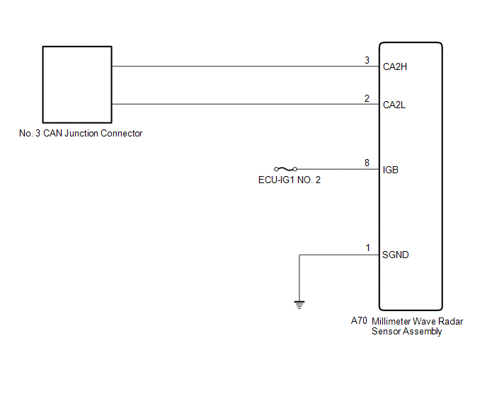
WIRING DIAGRAM
CAUTION / NOTICE / HINT
NOTICE:
- Before measuring the resistance of the CAN bus, turn the engine switch off and leave the vehicle for 1 minute or more without operating the key or any switches, or opening or closing the doors. After that, disconnect the cable from the negative (-) battery terminal and leave the vehicle for 1 minute or more before measuring the resistance.
-
After turning the engine switch off, waiting time may be required before disconnecting the cable from the negative (-) battery terminal. Therefore, make sure to read the disconnecting the cable from the negative (-) battery terminal notices before proceeding with work.
Click here
.gif)
-
Because the order of diagnosis is important to allow correct diagnosis, make sure to begin troubleshooting using How to Proceed with Troubleshooting when CAN communication system related DTCs are output.
Click here
- After performing repairs, perform the DTC check procedure and confirm that the DTCs are not output again.
- DTC check procedure: Drive the vehicle at a speed of 36 km/h (22 mph) or more for 7 seconds or more.
-
After the repair, perform the CAN bus check and check that all the ECUs and sensors connected to the CAN communication system are displayed.
Click here
- Inspect the fuses for circuits related to this system before performing the following procedure.
HINT:
- Operating the engine switch, any other switches or a door triggers related ECU and sensor communication on the CAN. This communication will cause the resistance value to change.
- Even after DTCs are cleared, if a DTC is stored again after driving the vehicle for a while, the malfunction may be occurring due to vibration of the vehicle. In such a case, wiggling the ECUs or wire harness while performing the inspection below may help determine the cause of the malfunction.
PROCEDURE
| 1. | CHECK FOR OPEN IN CAN BUS LINES (MILLIMETER WAVE RADAR SENSOR ASSEMBLY BRANCH LINE) |
(a) Disconnect the cable from the negative (-) battery terminal.
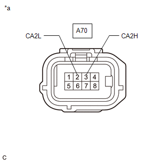
| (b) Disconnect the A70 millimeter wave radar sensor assembly connector. |
|
(c) Measure the resistance according to the value(s) in the table below.
Standard Resistance:
| Tester Connection | Condition | Specified Condition |
|---|---|---|
| A70-3 (CA2H) - A70-2 (CA2L) | Cable disconnected from negative (-) battery terminal | 54 to 69 Ω |
| NG | .gif) | REPAIR OR REPLACE CAN BRANCH LINES OR CONNECTOR (MILLIMETER WAVE RADAR SENSOR ASSEMBLY) |
|
.gif)
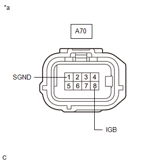
| 2. | CHECK HARNESS AND CONNECTOR (POWER SOURCE CIRCUIT) |
| (a) Measure the resistance according to the value(s) in the table below. Standard Resistance:
|
|
(b) Reconnect the cable to the negative (-) battery terminal.
(c) Measure the voltage according to the value(s) in the table below.
Standard Voltage:
| Tester Connection | Condition | Specified Condition |
|---|---|---|
| A70-8 (IGB) - Body ground | Engine switch on (IG) | 11 to 14 V |
| OK | | REPLACE MILLIMETER WAVE RADAR SENSOR ASSEMBLY |
| NG | | REPAIR OR REPLACE HARNESS OR CONNECTOR (POWER SOURCE CIRCUIT) |
 DCM Communication Stop Mode
DESCRIPTION Detection Item Symptom Trouble Area DCM Communication Stop Mode Either condition is met:
"DCM" is not displayed on the CAN Bus Check screen of the Techstream.
Click here ...
 Rear Television Camera Communication Stop Mode
DESCRIPTION Detection Item Symptom Trouble Area Rear Television Camera Communication Stop Mode Either condition is met:
"Parking Assist Monitor System" is not displayed on the CAN Bus ...
Other materials:
Lexus RX (RX 350L, RX450h) 2016-2026 Repair Manual > Wiper And Washer System: Rain Sensor Malfunction (B1400)
DESCRIPTION This DTC is stored when the rain sensor detects an internal malfunction. DTC No. Detection Item DTC Detection Condition Trouble Area Memory DTC Output from B1400 Rain Sensor Malfunction
When the battery voltage is 9.5 V or more, the rain sensor temperature is abno ...
Lexus RX (RX 350L, RX450h) 2016-2026 Repair Manual > Audio And Visual System (for 12.3 Inch Display): NTSC Disconnected (from Park Assist/Monitoring ECU) (B1535,C1622)
DESCRIPTION These DTCs are stored if the radio receiver assembly judges that the signals or signal lines between the rear television camera assembly and the multi-display assembly are not normal as a result of its self check. DTC No. Detection Item DTC Detection Condition Trouble Area B ...
Lexus RX (RX 350L, RX450h) 2016-{YEAR} Owners Manual
- For your information
- Pictorial index
- For safety and security
- Instrument cluster
- Operation of each component
- Driving
- Lexus Display Audio system
- Interior features
- Maintenance and care
- When trouble arises
- Vehicle specifications
- For owners
Lexus RX (RX 350L, RX450h) 2016-{YEAR} Repair Manual

0.0097