Lexus RX (RX 350L, RX450h) 2016-2026 Repair Manual: Open in Bus 1 Main Bus Line
DESCRIPTION
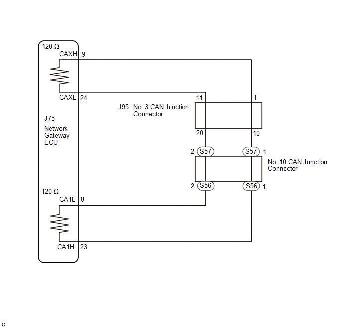
There may be an open circuit in one of the bus 1 main lines when the resistance between terminals 23 (CA1H) and 8 (CA1L) of the network gateway ECU is 70 Ω or higher.
| Symptom | Trouble Area |
|---|---|
| Resistance between terminals 23 (CA1H) and 8 (CA1L) of network gateway ECU is 70 Ω or higher. |
|
This malfunction is not related to the lines of a bus 1 branch or to ECUs or sensors connected to a bus 1 branch.
WIRING DIAGRAM
CAUTION / NOTICE / HINT
CAUTION:
When performing the confirmation driving pattern, obey all speed limits and traffic laws.
NOTICE:
- Before measuring the resistance of the CAN bus, turn the engine switch off and leave the vehicle for 1 minute or more without operating the key or any switches, or opening or closing the doors. After that, disconnect the cable from the negative (-) battery terminal and leave the vehicle for 1 minute or more before measuring the resistance.
-
After turning the engine switch off, waiting time may be required before disconnecting the cable from the negative (-) battery terminal. Therefore, make sure to read the disconnecting the cable from the negative (-) battery terminal notices before proceeding with work.
Click here
.gif)
-
Because the order of diagnosis is important to allow correct diagnosis, make sure to begin troubleshooting using How to Proceed with Troubleshooting when CAN communication system related DTCs are output.
Click here
-
After performing repairs, perform the DTC check procedure and confirm that the DTCs are not output again.
DTC check procedure: Turn the engine switch on (IG) and wait for 1 minute or more. Then operate the suspected malfunctioning system and drive the vehicle at 60 km/h (37 mph) or more for 5 minutes or more.
-
After the repair, perform the CAN bus check and check that all the ECUs and sensors connected to the CAN communication system are displayed.
Click here
HINT:
- Operating the engine switch, any other switches or a door triggers related ECU and sensor communication on the CAN. This communication will cause the resistance value to change.
- Even after DTCs are cleared, if a DTC is stored again after driving the vehicle for a while, the malfunction may be occurring due to vibration of the vehicle. In such a case, wiggling the ECUs or wire harness while performing the inspection below may help determine the cause of the malfunction.
PROCEDURE
| 1. | CHECK FOR OPEN IN CAN BUS LINES (NO. 10 CAN JUNCTION CONNECTOR) |
(a) Disconnect the cable from the negative (-) battery terminal.
(b) Disconnect the S56 and S57 No. 10 CAN junction connectors.
HINT:
- Connectors that connect to the CAN junction connector can be distinguished by the color of their CAN bus lines.
- Before disconnecting the connectors, make a note of where they are connected.
- Reconnecting the connectors to non-original positions on the CAN junction connector does not affect system performance. However, it is preferred to reconnect the connectors to their original positions to avoid negative effects on the wiring such as tension on the wiring harnesses, and to make future maintenance easier.
(c) Measure the resistance according to the value(s) in the table below.
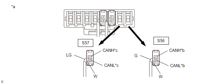
| *a | Rear view of wire harness connector (to No. 10 CAN Junction Connector) | *b | to Network Gateway ECU |
| *c | to No. 3 CAN Junction Connector | - | - |
| Code | Color (CANH Side) | Color (CANL Side) | Connected to |
|---|---|---|---|
| S56 | G | W | Network gateway ECU |
| S57 | LG | W | No. 3 CAN junction connector |
Standard Resistance:
| Tester Connection | Condition | Specified Condition | Connected to |
|---|---|---|---|
| S56-1 (CANH) - S56-2 (CANL) | Cable disconnected from negative (-) battery terminal | 108 to 132 Ω | Network gateway ECU |
| S57-1 (CANH) - S57-2 (CANL) | Cable disconnected from negative (-) battery terminal | 108 to 132 Ω | No. 3 CAN junction connector |
| Result | Proceed to |
|---|---|
| OK | A |
| NG (No. 3 CAN junction connector main lines) | B |
| NG (Network gateway ECU main lines) | C |
| A | .gif) | REPLACE NO. 10 CAN JUNCTION CONNECTOR |
| C | | GO TO STEP 4 |
|
.gif)
| 2. | CHECK FOR OPEN IN CAN BUS LINES (NO. 3 CAN JUNCTION CONNECTOR) |
(a) Reconnect the S56 and S57 No. 10 CAN junction connectors.
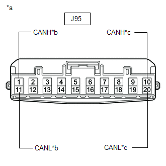
| (b) Disconnect the J95 No. 3 CAN junction connector. |
|
(c) Measure the resistance according to the value(s) in the table below.
Standard Resistance:
| Tester Connection | Condition | Specified Condition | Connected to |
|---|---|---|---|
| J95-1 (CANH) - J95-11 (CANL) | Cable disconnected from negative (-) battery terminal | 108 to 132 Ω | Network gateway ECU |
| J95-10 (CANH) - J95-20 (CANL) | Cable disconnected from negative (-) battery terminal | 108 to 132 Ω | No. 10 CAN junction connector |
| Result | Proceed to |
|---|---|
| OK | A |
| NG (No. 10 CAN junction connector main lines) | B |
| NG (Network gateway ECU main lines) | C |
| A | | REPLACE NO. 3 CAN JUNCTION CONNECTOR |
| B | | REPAIR OR REPLACE CAN MAIN BUS LINES OR CONNECTOR (NO. 3 CAN JUNCTION CONNECTOR - NO. 10 CAN JUNCTION CONNECTOR) |
|
| 3. | CHECK FOR OPEN IN CAN BUS LINES (NETWORK GATEWAY ECU - NO. 3 CAN JUNCTION CONNECTOR) |
(a) Reconnect the J95 No. 3 CAN junction connector.
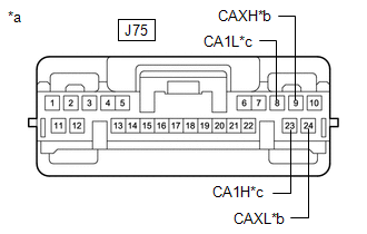
| (b) Disconnect the J75 network gateway ECU connector. |
|
(c) Measure the resistance according to the value(s) in the table below.
Standard Resistance:
| Tester Connection | Condition | Specified Condition |
|---|---|---|
| J75-9 (CAXH) - J75-23 (CA1H) | Cable disconnected from negative (-) battery terminal | Below 1 Ω |
| J75-8 (CA1L) - J75-24 (CAXL) | Cable disconnected from negative (-) battery terminal | Below 1 Ω |
| OK | | REPLACE NETWORK GATEWAY ECU |
| NG | | REPAIR OR REPLACE CAN MAIN BUS LINES OR CONNECTOR (NETWORK GATEWAY ECU - NO. 3 CAN JUNCTION CONNECTOR) |
| 4. | CHECK FOR OPEN IN CAN BUS LINES (NETWORK GATEWAY ECU - NO. 10 CAN JUNCTION CONNECTOR) |
(a) Reconnect the S56 and S57 No. 10 CAN junction connectors.
| (b) Disconnect the J75 network gateway ECU connector. |
|
(c) Measure the resistance according to the value(s) in the table below.
Standard Resistance:
| Tester Connection | Condition | Specified Condition |
|---|---|---|
| J75-9 (CAXH) - J75-23 (CA1H) | Cable disconnected from negative (-) battery terminal | Below 1 Ω |
| J75-8 (CA1L) - J75-24 (CAXL) | Cable disconnected from negative (-) battery terminal | Below 1 Ω |
| OK | | REPLACE NETWORK GATEWAY ECU |
| NG | | REPAIR OR REPLACE CAN MAIN BUS LINES OR CONNECTOR (NETWORK GATEWAY ECU - NO. 10 CAN JUNCTION CONNECTOR) |
 Combination Meter Mirror ECU Communication Stop Mode
DESCRIPTION Detection Item Symptom Trouble Area Combination Meter Mirror ECU Communication Stop Mode Either condition is met:
"Head Up Display" is not displayed on the CAN Bus Check sc ...
 Check Bus 1 Lines for Short Circuit
DESCRIPTION There may be a short circuit between the bus 1 main lines and/or bus 1 branch lines when the resistance between terminals 23 (CA1H) and 8 (CA1L) of the network gateway ECU is below 54 Ω. ...
Other materials:
Lexus RX (RX 350L, RX450h) 2016-2026 Repair Manual > Audio And Visual System (for 12.3 Inch Display): Stereo Component Amplifier Malfunction (B15A3)
DESCRIPTION This DTC is stored when a malfunction occurs in the stereo component amplifier assembly. DTC No. Detection Item DTC Detection Condition Trouble Area B15A3 Stereo Component Amplifier Malfunction When any of the following conditions is met:
Internal power supply malfunc ...
Lexus RX (RX 350L, RX450h) 2016-2026 Repair Manual > Power Seat Switch(w/o Seat Position Memory System): Installation
INSTALLATION CAUTION / NOTICE / HINT CAUTION: Wear protective gloves. Sharp areas on the parts may injure your hands. HINT:
Use the same procedure for the RH side and LH side.
The following procedure is for the LH side.
PROCEDURE 1. INSTALL FRONT POWER SEAT SWITCH (a) Install the front po ...
Lexus RX (RX 350L, RX450h) 2016-{YEAR} Owners Manual
- For your information
- Pictorial index
- For safety and security
- Instrument cluster
- Operation of each component
- Driving
- Lexus Display Audio system
- Interior features
- Maintenance and care
- When trouble arises
- Vehicle specifications
- For owners
Lexus RX (RX 350L, RX450h) 2016-{YEAR} Repair Manual

0.0103