Lexus RX (RX 350L, RX450h) 2016-2026 Repair Manual: Check Bus 1 Line for Short to +B
DESCRIPTION
There may be a short circuit between one of the CAN bus lines and +B when there is no resistance between terminal 23 (CA1H) of the network gateway ECU and terminal 16 (BAT) of the DLC3, or terminal 8 (CA1L) of the network gateway ECU and terminal 16 (BAT) of the DLC3.
| Symptom | Trouble Area |
|---|---|
| There is no resistance between terminal 23 (CA1H) of the network gateway ECU and terminal 16 (BAT) of the DLC3, or terminal 8 (CA1L) of the network gateway ECU and terminal 16 (BAT) of the DLC3. |
|
WIRING DIAGRAM
.png)
.png)
CAUTION / NOTICE / HINT
CAUTION:
When performing the confirmation driving pattern, obey all speed limits and traffic laws.
NOTICE:
- Before measuring the resistance of the CAN bus, turn the engine switch off and leave the vehicle for 1 minute or more without operating the key or any switches, or opening or closing the doors. After that, disconnect the cable from the negative (-) battery terminal and leave the vehicle for 1 minute or more before measuring the resistance.
-
After turning the engine switch off, waiting time may be required before disconnecting the cable from the negative (-) battery terminal. Therefore, make sure to read the disconnecting the cable from the negative (-) battery terminal notices before proceeding with work.
Click here
.gif)
-
Because the order of diagnosis is important to allow correct diagnosis, make sure to begin troubleshooting using How to Proceed with Troubleshooting when CAN communication system related DTCs are output.
Click here
-
After performing repairs, perform the DTC check procedure and confirm that the DTCs are not output again.
DTC check procedure: Turn the engine switch on (IG) and wait for 1 minute or more. Then operate the suspected malfunctioning system and drive the vehicle at 60 km/h (37 mph) or more for 5 minutes or more.
-
After the repair, perform the CAN bus check and check that all the ECUs and sensors connected to the CAN communication system are displayed.
Click here
HINT:
- Operating the engine switch, any other switches or a door triggers related ECU and sensor communication on the CAN. This communication will cause the resistance value to change.
- Even after DTCs are cleared, if a DTC is stored again after driving the vehicle for a while, the malfunction may be occurring due to vibration of the vehicle. In such a case, wiggling the ECUs or wire harness while performing the inspection below may help determine the cause of the malfunction.
PROCEDURE
| 1. | CHECK FOR SHORT TO +B IN CAN BUS LINE (NETWORK GATEWAY ECU) |
(a) Disconnect the cable from the negative (-) battery terminal.
(b) Disconnect the J75 network gateway ECU connector.
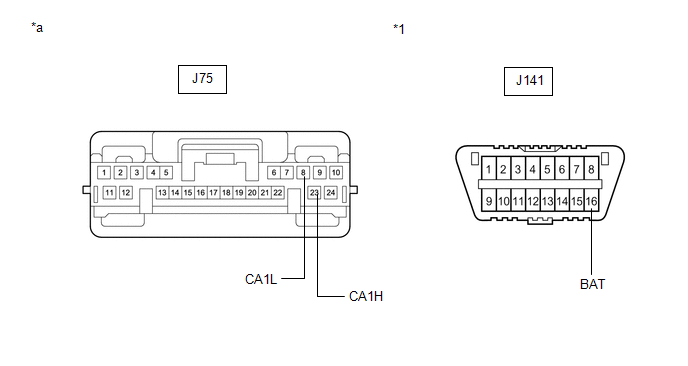
| *1 | DLC3 | - | - |
| *a | Front view of wire harness connector (to Network Gateway ECU) | - | - |
(c) Measure the resistance according to the value(s) in the table below.
Standard Resistance:
| Tester Connection | Condition | Specified Condition |
|---|---|---|
| J75-23 (CA1H) - J141-16 (BAT) | Cable disconnected from negative (-) battery terminal | 6 kΩ or higher |
| J75-8 (CA1L) - J141-16 (BAT) |
| OK | .gif) | REPLACE NETWORK GATEWAY ECU |
|
.gif)
| 2. | CHECK FOR SHORT TO +B IN CAN BUS LINE (NO. 10 CAN JUNCTION CONNECTOR) |
(a) Reconnect the J75 network gateway ECU connector.
(b) Disconnect the S56, S57, S58 and S59 No. 10 CAN junction connectors.
HINT:
- Connectors that connect to the CAN junction connector can be distinguished by the color of their CAN bus lines.
- Before disconnecting the connectors, make a note of where they are connected.
- Reconnecting the connectors to non-original positions on the CAN junction connector does not affect system performance. However, it is preferred to reconnect the connectors to their original positions to avoid negative effects on the wiring such as tension on the wiring harnesses, and to make future maintenance easier.
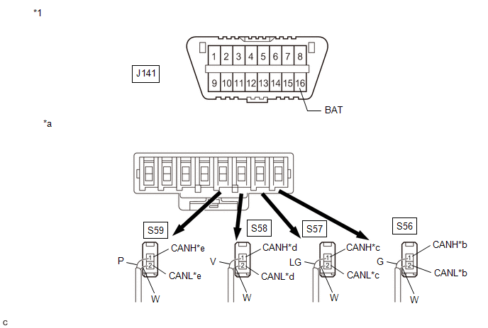
| *1 | DLC3 | - | - |
| *a | Rear view of wire harness connector (to No. 10 CAN Junction Connector) | *b | to Network Gateway ECU |
| *c | to No. 3 CAN Junction Connector | *d | to Blind Spot Monitor Sensor LH (w/ Blind Spot Monitor System) |
| *e | to Rear Television Camera Assembly | - | - |
| Code | Color (CANH Side) | Color (CANL Side) | Connected to |
|---|---|---|---|
| S56 | G | W | Network gateway ECU |
| S57 | LG | W | No. 3 CAN junction connector |
| S58 | V | W | Blind spot monitor sensor LH |
| S59 | P | W | Rear television camera assembly |
(c) Measure the resistance according to the value(s) in the table below.
Standard Resistance:
| Tester Connection | Condition | Specified Condition | Connected to |
|---|---|---|---|
| S56-1 (CANH) - J141-16 (BAT) | Cable disconnected from negative (-) battery terminal | 6 kΩ or higher | Network gateway ECU |
| S56-2 (CANL) - J141-16 (BAT) | |||
| S57-1 (CANH) - J141-16 (BAT) | Cable disconnected from negative (-) battery terminal | 6 kΩ or higher | No. 3 CAN junction connector |
| S57-2 (CANL) - J141-16 (BAT) | |||
| S58-1 (CANH) - J141-16 (BAT) | Cable disconnected from negative (-) battery terminal | 6 kΩ or higher | Blind spot monitor sensor LH* |
| S58-2 (CANL) - J141-16 (BAT) | |||
| S59-1 (CANH) - J141-16 (BAT) | Cable disconnected from negative (-) battery terminal | 6 kΩ or higher | Rear television camera assembly |
| S59-2 (CANL) - J141-16 (BAT) |
- *: w/ Blind Spot Monitor System
| Result | Proceed to |
|---|---|
| OK | A |
| NG (Network gateway ECU main line) | B |
| NG (ECU or sensor bus line) | C |
| NG (No. 3 CAN junction connector main line) | D |
| A | | REPLACE NO. 10 CAN JUNCTION CONNECTOR |
| B | | REPAIR OR REPLACE CAN MAIN BUS LINE OR CONNECTOR (NETWORK GATEWAY ECU - NO. 10 CAN JUNCTION CONNECTOR) |
| C | | GO TO STEP 4 |
|
| 3. | CHECK FOR SHORT TO +B IN CAN BUS LINE (NO. 3 CAN JUNCTION CONNECTOR) |
(a) Reconnect the S56, S57, S58 and S59 No. 10 CAN junction connectors.
(b) Disconnect the J95 No. 3 CAN junction connector.
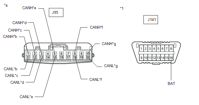
| *1 | DLC3 | - | - |
| *a | Front view of wire harness connector (to No. 3 CAN Junction Connector) | *b | to Network Gateway ECU |
| *c | to Parking Assist ECU (w/ Panoramic View Monitor System) | *d | to Clearance Warning ECU Assembly (w/ Intuitive Parking Assist System) |
| *e | to Millimeter Wave Radar Sensor Assembly | *f | to Forward Recognition Camera |
| *g | to No. 10 CAN Junction Connector | - | - |
(c) Measure the resistance according to the value(s) in the table below.
Standard Resistance:
| Tester Connection | Condition | Specified Condition | Connected to |
|---|---|---|---|
| J95-1 (CANH) - J141-16 (BAT) | Cable disconnected from negative (-) battery terminal | 6 kΩ or higher | Network gateway ECU |
| J95-11 (CANL) - J141-16 (BAT) | |||
| J95-2 (CANH) - J141-16 (BAT) | Cable disconnected from negative (-) battery terminal | 6 kΩ or higher | Parking assist ECU*1 |
| J95-12 (CANL) - J141-16 (BAT) | |||
| J95-3 (CANH) - J141-16 (BAT) | Cable disconnected from negative (-) battery terminal | 6 kΩ or higher | Clearance warning ECU assembly*2 |
| J95-13 (CANL) - J141-16 (BAT) | |||
| J95-5 (CANH) - J141-16 (BAT) | Cable disconnected from negative (-) battery terminal | 6 kΩ or higher | Millimeter wave radar sensor assembly |
| J95-15 (CANL) - J141-16 (BAT) | |||
| J95-8 (CANH) - J141-16 (BAT) | Cable disconnected from negative (-) battery terminal | 6 kΩ or higher | Forward recognition camera |
| J95-18 (CANL) - J141-16 (BAT) | |||
| J95-10 (CANH) - J141-16 (BAT) | Cable disconnected from negative (-) battery terminal | 6 kΩ or higher | No. 10 CAN junction connector |
| J95-20 (CANL) - J141-16 (BAT) |
- *1: w/ Panoramic View Monitor System
- *2: w/ Intuitive Parking Assist System
| Result | Proceed to |
|---|---|
| OK | A |
| NG (No. 10 CAN junction connector main line) | B |
| NG (ECU or sensor bus line) | C |
| NG (Network gateway ECU main line) | D |
| A | | REPLACE NO. 3 CAN JUNCTION CONNECTOR |
| B | | REPAIR OR REPLACE CAN MAIN BUS LINE OR CONNECTOR (NO. 3 CAN JUNCTION CONNECTOR - NO. 10 CAN JUNCTION CONNECTOR) |
| D | | REPAIR OR REPLACE CAN MAIN BUS LINE OR CONNECTOR (NETWORK GATEWAY ECU - NO. 3 CAN JUNCTION CONNECTOR) |
|
| 4. | CHECK FOR SHORT TO +B IN CAN BUS LINE (ECU, SENSOR) |
(a) Reconnect all wire harness connectors.
(b) Disconnect the connector that includes terminals CANH and CANL from the ECU or sensor to which the bus line shorted to +B is connected.
Click here
(c) Measure the resistance according to the value(s) in the table below.
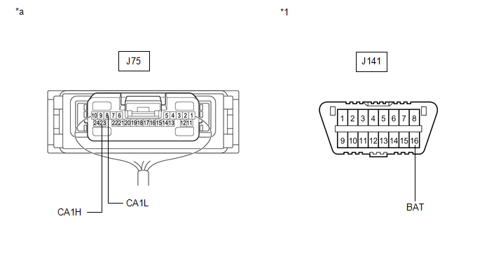
| *1 | DLC3 | - | - |
| *a | Component with harness connected (Network Gateway ECU) | - | - |
Standard Resistance:
| Tester Connection | Condition | Specified Condition |
|---|---|---|
| J75-23 (CA1H) - J141-16 (BAT) | Cable disconnected from negative (-) battery terminal | 6 kΩ or higher |
| J75-8 (CA1L) - J141-16 (BAT) |
HINT:
If the resistance changes to 6 kΩ or higher when the connector is disconnected from the ECU or sensor, there may be a short in the ECU or sensor.
| OK | | REPLACE CORRESPONDING ECU OR SENSOR |
| NG | | REPAIR OR REPLACE CORRESPONDING ECU OR SENSOR CAN BUS LINE OR CONNECTOR |
 Check Bus 1 Lines for Short Circuit
DESCRIPTION There may be a short circuit between the bus 1 main lines and/or bus 1 branch lines when the resistance between terminals 23 (CA1H) and 8 (CA1L) of the network gateway ECU is below 54 Ω. ...
 Open in One Side of Bus 1 Branch Line
DESCRIPTION If an ECU or sensor is not displayed on the CAN Bus Check screen of the Techstream and some ECUs and sensors repeatedly appear and disappear from the screen when the CAN main bus lines are ...
Other materials:
Lexus RX (RX 350L, RX450h) 2016-2026 Repair Manual > Automatic Transaxle System: Pressure Control Solenoid "G" Actuator Stuck Off (P28077F)
DESCRIPTION Based on signals from the transmission revolution sensors (NT, NC3 and NC), the actual gear is detected. The ECM compares the actual gear with the shift schedule in the ECM memory to detect mechanical malfunction of the shift solenoid valves, transmission valve body assembly and automati ...
Lexus RX (RX 350L, RX450h) 2016-2026 Repair Manual > Purge Valve: Removal
REMOVAL PROCEDURE 1. REMOVE V-BANK COVER SUB-ASSEMBLY Click here 2. REMOVE PURGE VALVE (PURGE VSV) (for TMMC Made) (a) Disconnect the purge valve (purge VSV) connector. *1 No. 1 Fuel Vapor Feed Hose *2 Fuel Vapor Feed Hose (b) Slide the clip and disconnect the fue ...
Lexus RX (RX 350L, RX450h) 2016-{YEAR} Owners Manual
- For your information
- Pictorial index
- For safety and security
- Instrument cluster
- Operation of each component
- Driving
- Lexus Display Audio system
- Interior features
- Maintenance and care
- When trouble arises
- Vehicle specifications
- For owners
Lexus RX (RX 350L, RX450h) 2016-{YEAR} Repair Manual

0.0095