Lexus RX (RX 350L, RX450h) 2016-2026 Repair Manual: Check Bus 5 Line for Short to GND
DESCRIPTION
There may be a short circuit between one of the CAN bus lines and GND when there is no resistance between terminal 15 (CA5H) of the network gateway ECU and terminal 4 (CG) of the DLC3, or terminal 16 (CA5L) of the network gateway ECU and terminal 4 (CG) of the DLC3.
| Symptom | Trouble Area |
|---|---|
| No resistance exists between terminal 15 (CA5H) of the network gateway ECU and terminal 4 (CG) of the DLC3, or terminal 16 (CA5L) of the network gateway ECU and terminal 4 (CG) of the DLC3. |
|
WIRING DIAGRAM
.png)
CAUTION / NOTICE / HINT
NOTICE:
- Before measuring the resistance of the CAN bus, turn the engine switch off and leave the vehicle for 1 minute or more without operating the key or any switches, or opening or closing the doors. After that, disconnect the cable from the negative (-) battery terminal and leave the vehicle for 1 minute or more before measuring the resistance.
-
After turning the engine switch off, waiting time may be required before disconnecting the cable from the negative (-) battery terminal. Therefore, make sure to read the disconnecting the cable from the negative (-) battery terminal notices before proceeding with work.
Click here
.gif)
-
Because the order of diagnosis is important to allow correct diagnosis, make sure to begin troubleshooting using How to Proceed with Troubleshooting when CAN communication system related DTCs are output.
Click here
- After performing repairs, perform the DTC check procedure and confirm that the DTCs are not output again.
- DTC check procedure: Drive the vehicle at a speed of 5 km/h (3 mph) or more for 52 seconds or more.
-
After the repair, perform the CAN bus check and check that all the ECUs and sensors connected to the CAN communication system are displayed.
Click here
-
Before replacing the certification ECU (smart key ECU assembly), refer to the smart access system with push-button start (for Start Function) Precaution.
Click here
-
If the main body ECU (multiplex network body ECU) is replaced, refer to Registration.
Click here
HINT:
- Operating the engine switch, any other switches or a door triggers related ECU and sensor communication on the CAN. This communication will cause the resistance value to change.
- Even after DTCs are cleared, if a DTC is stored again after driving the vehicle for a while, the malfunction may be occurring due to vibration of the vehicle. In such a case, wiggling the ECUs or wire harness while performing the inspection below may help determine the cause of the malfunction.
PROCEDURE
| 1. | CHECK FOR SHORT TO GND IN CAN BUS LINE (NETWORK GATEWAY ECU) |
(a) Disconnect the cable from the negative (-) battery terminal.
(b) Disconnect the J75 network gateway ECU connector.
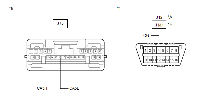
| *A | for DLC3 Connector Type A | *B | for DLC3 Connector Type B |
| *1 | DLC3 | - | - |
| *a | Front view of wire harness connector (to Network Gateway ECU) | - | - |
(c) Measure the resistance according to the value(s) in the table below.
Standard Resistance:
for DLC3 Connector Type A| Tester Connection | Condition | Specified Condition |
|---|---|---|
| J75-15 (CA5H) - J12-4 (CG) | Cable disconnected from negative (-) battery terminal | 200 Ω or higher |
| J75-16 (CA5L) - J12-4 (CG) |
| Tester Connection | Condition | Specified Condition |
|---|---|---|
| J75-15 (CA5H) - J141-4 (CG) | Cable disconnected from negative (-) battery terminal | 200 Ω or higher |
| J75-16 (CA5L) - J141-4 (CG) |
| OK | .gif) | REPLACE NETWORK GATEWAY ECU |
|
.gif)
| 2. | CHECK FOR SHORT TO GND IN CAN BUS LINE (NO. 5 CAN JUNCTION CONNECTOR) |
(a) Disconnect the J97 No. 5 CAN junction connector.
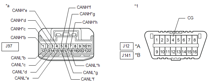
| *A | for DLC3 Connector Type A | *B | for DLC3 Connector Type B |
| *1 | DLC3 | - | - |
| *a | Front view of wire harness connector (to No. 5 CAN Junction Connector) | *b | to Network Gateway ECU |
| *c | to Combination Meter Mirror ECU (Headup Display) (w/ Headup Display System) | *d | to Headlight ECU Sub-assembly LH (w/ Automatic Headlight Beam Level Control System) |
| *e | to Main Body ECU (Multiplex Network Body ECU) | *f | to Air Conditioning Amplifier Assembly |
| *g | to Combination Meter Assembly | *h | to Certification ECU (Smart Key ECU Assembly) |
(b) Measure the resistance according to the value(s) in the table below.
Standard Resistance:
for DLC3 Connector Type A| Tester Connection | Condition | Specified Condition | Connected to |
|---|---|---|---|
|
*1: w/ Headup Display System
*2: w/ Automatic Headlight Beam Level Control System | |||
| J97-1 (CANH) - J12-4 (CG) | Cable disconnected from negative (-) battery terminal | 200 Ω or higher | Network gateway ECU |
| J97-12 (CANL) - J12-4 (CG) | |||
| J97-2 (CANH) - J12-4 (CG) | Cable disconnected from negative (-) battery terminal | 200 Ω or higher | Combination meter mirror ECU (headup display)*1 |
| J97-13 (CANL) - J12-4 (CG) | |||
| J97-3 (CANH) - J12-4 (CG) | Cable disconnected from negative (-) battery terminal | 200 Ω or higher | Headlight ECU sub-assembly LH*2 |
| J97-14 (CANL) - J12-4 (CG) | |||
| J97-4 (CANH) - J12-4 (CG) | Cable disconnected from negative (-) battery terminal | 200 Ω or higher | Main body ECU (multiplex network body ECU) |
| J97-15 (CANL) - J12-4 (CG) | |||
| J97-5 (CANH) - J12-4 (CG) | Cable disconnected from negative (-) battery terminal | 200 Ω or higher | Air conditioning amplifier assembly |
| J97-16 (CANL) - J12-4 (CG) | |||
| J97-6 (CANH) - J12-4 (CG) | Cable disconnected from negative (-) battery terminal | 200 Ω or higher | Combination meter assembly |
| J97-17 (CANL) - J12-4 (CG) | |||
| J97-7 (CANH) - J12-4 (CG) | Cable disconnected from negative (-) battery terminal | 200 Ω or higher | Certification ECU (smart key ECU assembly) |
| J97-18 (CANL) - J12-4 (CG) | |||
| Tester Connection | Condition | Specified Condition | Connected to |
|---|---|---|---|
|
*1: w/ Headup Display System
*2: w/ Automatic Headlight Beam Level Control System | |||
| J97-1 (CANH) - J141-4 (CG) | Cable disconnected from negative (-) battery terminal | 200 Ω or higher | Network gateway ECU |
| J97-12 (CANL) - J141-4 (CG) | |||
| J97-2 (CANH) - J141-4 (CG) | Cable disconnected from negative (-) battery terminal | 200 Ω or higher | Combination meter mirror ECU (headup display)*1 |
| J97-13 (CANL) - J141-4 (CG) | |||
| J97-3 (CANH) - J141-4 (CG) | Cable disconnected from negative (-) battery terminal | 200 Ω or higher | Headlight ECU sub-assembly LH*2 |
| J97-14 (CANL) - J141-4 (CG) | |||
| J97-4 (CANH) - J141-4 (CG) | Cable disconnected from negative (-) battery terminal | 200 Ω or higher | Main body ECU (multiplex network body ECU) |
| J97-15 (CANL) - J141-4 (CG) | |||
| J97-5 (CANH) - J141-4 (CG) | Cable disconnected from negative (-) battery terminal | 200 Ω or higher | Air conditioning amplifier assembly |
| J97-16 (CANL) - J141-4 (CG) | |||
| J97-6 (CANH) - J141-4 (CG) | Cable disconnected from negative (-) battery terminal | 200 Ω or higher | Combination meter assembly |
| J97-17 (CANL) - J141-4 (CG) | |||
| J97-7 (CANH) - J141-4 (CG) | Cable disconnected from negative (-) battery terminal | 200 Ω or higher | Certification ECU (smart key ECU assembly) |
| J97-18 (CANL) - J141-4 (CG) | |||
| Result | Proceed to |
|---|---|
| OK | A |
| NG (Network gateway ECU bus line) | B |
| NG (ECU or sensor bus line) | C |
| A | | REPLACE NO. 5 CAN JUNCTION CONNECTOR |
| B | | REPAIR OR REPLACE CAN MAIN BUS LINE OR CONNECTOR (NETWORK GATEWAY ECU - NO. 5 CAN JUNCTION CONNECTOR) |
|
| 3. | CHECK FOR SHORT TO GND IN CAN BUS LINE (ECU, SENSOR) |
(a) Reconnect all wire harness connectors.
(b) Disconnect the connector that includes terminals CANH and CANL from the ECU or sensor to which the bus line shorted to GND is connected.
Click here
(c) Measure the resistance according to the value(s) in the table below.
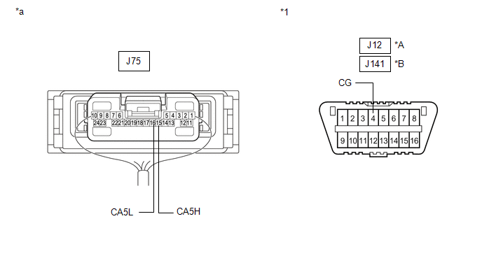
| *A | for DLC3 Connector Type A | *B | for DLC3 Connector Type B |
| *1 | DLC3 | - | - |
| *a | Component with harness connected (Network Gateway ECU) | - | - |
Standard Resistance:
for DLC3 Connector Type A| Tester Connection | Condition | Specified Condition |
|---|---|---|
| J75-15 (CA5H) - J12-4 (CG) | Cable disconnected from negative (-) battery terminal | 200 Ω or higher |
| J75-16 (CA5L) - J12-4 (CG) |
| Tester Connection | Condition | Specified Condition |
|---|---|---|
| J75-15 (CA5H) - J141-4 (CG) | Cable disconnected from negative (-) battery terminal | 200 Ω or higher |
| J75-16 (CA5L) - J141-4 (CG) |
HINT:
If the resistance changes to 200 Ω or higher when the connector is disconnected from the ECU or sensor, there may be a short in the ECU or sensor.
| OK | | REPLACE CORRESPONDING ECU OR SENSOR |
| NG | | REPAIR OR REPLACE CORRESPONDING ECU OR SENSOR CAN BUS LINE OR CONNECTOR |
 Check Bus 5 Line for Short to +B
DESCRIPTION There may be a short circuit between one of the CAN bus lines and +B when no resistance exists between terminal 15 (CA5H) of the network gateway ECU and terminal 16 (BAT) of the DLC3, or t ...
 Check Bus 5 Lines for Short Circuit
DESCRIPTION There may be a short circuit between the bus 5 main lines and/or bus 5 branch lines when the resistance between terminals 15 (CA5H) and 16 (CA5L) of the network gateway ECU is below 54 Ω. ...
Other materials:
Lexus RX (RX 350L, RX450h) 2016-2026 Repair Manual > Air Conditioning System: Evaporator Temperature Circuit (B1417/17)
DESCRIPTION The No. 2 air conditioning harness assembly is installed on the evaporator in the rear air conditioner unit to detect the temperature of the cooled air that has passed through the evaporator, which is used to control the air conditioning system. It sends signals to the air conditioning a ...
Lexus RX (RX 350L, RX450h) 2016-2026 Repair Manual > Air Conditioning System: Air Conditioning Control Panel Circuit
DESCRIPTION The radio receiver assembly (A/C control panel) switch signals are sent to the air conditioning amplifier assembly via CAN communication. WIRING DIAGRAM CAUTION / NOTICE / HINT NOTICE: Inspect the fuses for circuits related to this system before performing the following procedure. PROCE ...
Lexus RX (RX 350L, RX450h) 2016-{YEAR} Owners Manual
- For your information
- Pictorial index
- For safety and security
- Instrument cluster
- Operation of each component
- Driving
- Lexus Display Audio system
- Interior features
- Maintenance and care
- When trouble arises
- Vehicle specifications
- For owners
Lexus RX (RX 350L, RX450h) 2016-{YEAR} Repair Manual

0.0104