Lexus RX (RX 350L, RX450h) 2016-2026 Repair Manual: Start Up Signal Circuit between Radio Receiver Assembly and Navigation ECU
DESCRIPTION
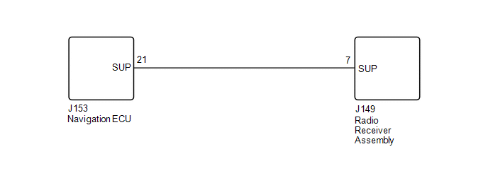
This circuit includes the navigation ECU and radio receiver assembly.
WIRING DIAGRAM
PROCEDURE
| 1. | CHECK HARNESS AND CONNECTOR (RADIO RECEIVER ASSEMBLY - NAVIGATION ECU) |
(a) Disconnect the J149 radio receiver assembly connector.
(b) Disconnect the J153 navigation ECU connector.
(c) Measure the resistance according to the value(s) in the table below.
Standard Resistance:
| Tester Connection | Condition | Specified Condition |
|---|---|---|
| J149-7 (SUP) - J153-21 (SUP) | Always | Below 1 Ω |
| J149-7 (SUP) or J153-21 (SUP) - Body ground | Always | 10 kΩ or higher |
| OK |  | PROCEED TO NEXT SUSPECTED AREA SHOWN IN PROBLEM SYMPTOMS TABLE |
| NG | | REPAIR OR REPLACE HARNESS OR CONNECTOR |
 Reverse Signal Circuit between Radio Receiver Assembly and Navigation ECU
DESCRIPTION This circuit includes the navigation ECU and radio receiver assembly. WIRING DIAGRAM PROCEDURE 1. CHECK HARNESS AND CONNECTOR (RADIO RECEIVER ASSEMBLY - NAVIGATION ECU) (a) Disco ...
 Microphone Circuit
DESCRIPTION
The radio receiver assembly and telephone microphone assembly are connected to each other using the microphone connection detection signal lines.
Using this circuit, the radio receive ...
Other materials:
Lexus RX (RX 350L, RX450h) 2016-2026 Repair Manual > Instrument Panel Speaker: Removal
REMOVAL CAUTION / NOTICE / HINT for Side:
Use the same procedure for the RH side and LH side.
The following procedure is for the LH side.
PROCEDURE 1. REMOVE NO. 1 INSTRUMENT PANEL SPEAKER PANEL SUB-ASSEMBLY (for Side) Click here 2. REMOVE FRONT NO. 2 SPEAKER ASSEMBLY (for Side) NOTICE: ...
Lexus RX (RX 350L, RX450h) 2016-2026 Repair Manual > Curtain Shield Airbag Assembly (w/ Rear No. 2 Seat): Removal
REMOVAL CAUTION / NOTICE / HINT The necessary procedures (adjustment, calibration, initialization, or registration) that must be performed after parts are removed, installed, or replaced during the curtain shield airbag assembly removal/installation are shown below. Necessary Procedure After Parts R ...
Lexus RX (RX 350L, RX450h) 2016-{YEAR} Owners Manual
- For your information
- Pictorial index
- For safety and security
- Instrument cluster
- Operation of each component
- Driving
- Lexus Display Audio system
- Interior features
- Maintenance and care
- When trouble arises
- Vehicle specifications
- For owners
Lexus RX (RX 350L, RX450h) 2016-{YEAR} Repair Manual

0.0138