Lexus RX (RX 350L, RX450h) 2016-2026 Repair Manual: Microphone Circuit
DESCRIPTION
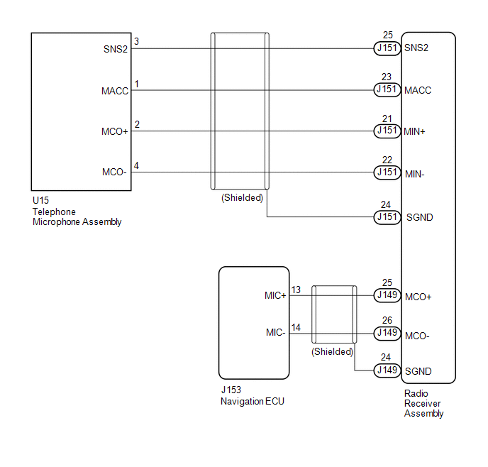
- The radio receiver assembly and telephone microphone assembly are connected to each other using the microphone connection detection signal lines.
- Using this circuit, the radio receiver assembly sends power to the telephone microphone assembly, and the telephone microphone assembly sends microphone signals to the radio receiver assembly and navigation ECU.
WIRING DIAGRAM
CAUTION / NOTICE / HINT
NOTICE:
Depending on the parts that are replaced during vehicle inspection or maintenance, performing initialization, registration or calibration may be needed. Refer to Precaution for Audio and Visual System.
Click here .gif)
PROCEDURE
| 1. | CHECK MICROPHONE AND VOICE RECOGNITION (INPUT TO NAVIGATION ECU) |
| (a) Enter the "Microphone Check" screen. Refer to Check Microphone (Input to navigation ECU) in Operation Check. Click here |
|
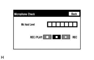
(b) When voice is input into the microphone, check that the microphone input level meter changes according to the input voice.
OK:
Check result is normal.
| OK | .gif) | PROCEED TO NEXT SUSPECTED AREA SHOWN IN PROBLEM SYMPTOMS TABLE |
|
.gif)
| 2. | CHECK MICROPHONE AND VOICE RECOGNITION (INPUT TO RADIO RECEIVER ASSEMBLY) |
| (a) Enter the "Microphone Check" screen. Refer to Check Microphone (Input to radio receiver assembly) in Operation Check. Click here |
|
(b) When voice is input into the microphone, check that the microphone input level meter changes according to the input voice.
OK:
Check result is normal.
| NG | | GO TO STEP 5 |
|
| 3. | CHECK HARNESS AND CONNECTOR (RADIO RECEIVER ASSEMBLY - NAVIGATION ECU) |
(a) Disconnect the J149 radio receiver assembly connector.
(b) Disconnect the J153 navigation ECU connector.
(c) Measure the resistance according to the value(s) in the table below.
Standard Resistance:
| Tester Connection | Condition | Specified Condition |
|---|---|---|
| J149-25 (MCO+) - J153-13 (MIC+) | Always | Below 1 Ω |
| J149-26 (MCO-) - J153-14 (MIC-) | Always | Below 1 Ω |
| J149-25 (MCO+) or J153-13 (MIC+) - Body ground | Always | 10 kΩ or higher |
| J149-26 (MCO-) or J153-14 (MIC-) - Body ground | Always | 10 kΩ or higher |
| J149-24 (SGND) - Body ground | Always | 10 kΩ or higher |
| NG | | REPAIR OR REPLACE HARNESS OR CONNECTOR |
|
| 4. | INSPECT RADIO RECEIVER ASSEMBLY (OUTPUT TO NAVIGATION ECU) |
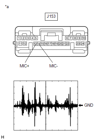
(a) Disconnect the J153 navigation ECU connector.
(b) Turn the engine switch on (ACC).
| (c) Check the signal waveform according to the condition(s) in the table below.
OK: The waveform is similar to that shown in the illustration. HINT: The oscilloscope waveform shown in the illustration is an example for reference only. |
|
| OK | | PROCEED TO NEXT SUSPECTED AREA SHOWN IN PROBLEM SYMPTOMS TABLE |
| NG | | REPLACE RADIO RECEIVER ASSEMBLY |
| 5. | CHECK HARNESS AND CONNECTOR (RADIO RECEIVER ASSEMBLY - TELEPHONE MICROPHONE ASSEMBLY) |
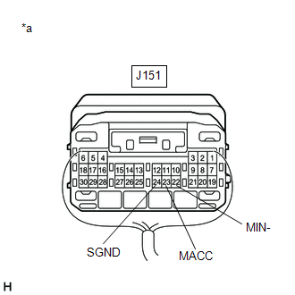
(a) Disconnect the J151 radio receiver assembly connector.
(b) Disconnect the U15 telephone microphone assembly connector.
(c) Measure the resistance according to the value(s) in the table below.
Standard Resistance:
| Tester Connection | Condition | Specified Condition |
|---|---|---|
| J151-25 (SNS2) - U15-3 (SNS2) | Always | Below 1 Ω |
| J151-23 (MACC) - U15-1 (MACC) | Always | Below 1 Ω |
| J151-21 (MIN+) - U15-2 (MCO+) | Always | Below 1 Ω |
| J151-22 (MIN-) - U15-4 (MCO-) | Always | Below 1 Ω |
| J151-25 (SNS2) or U15-3 (SNS2) - Body ground | Always | 10 kΩ or higher |
| J151-23 (MACC) or U15-1 (MACC) - Body ground | Always | 10 kΩ or higher |
| J151-21 (MIN+) or U15-2 (MCO+) - Body ground | Always | 10 kΩ or higher |
| J151-22 (MIN-) or U15-4 (MCO-) - Body ground | Always | 10 kΩ or higher |
| J151-24 (SGND) - Body ground | Always | 10 kΩ or higher |
| NG | | REPAIR OR REPLACE HARNESS OR CONNECTOR |
|
| 6. | CHECK RADIO RECEIVER ASSEMBLY |
| (a) Remove the radio receiver assembly with the connector(s) still connected. |
|
(b) Measure the voltage according to the value(s) in the table below.
Standard Voltage:
| Tester Connection | Condition | Specified Condition |
|---|---|---|
| J151-23 (MACC) - Body ground | Engine switch on (ACC) | 4 to 6 V |
(c) Measure the resistance according to the value(s) in the table below.
Standard Resistance:
| Tester Connection | Condition | Specified Condition |
|---|---|---|
| J151-22 (MIN-) - Body ground | Always | Below 1 Ω |
| J151-24 (SGND) - Body ground | Always | Below 1 Ω |
| NG | | REPLACE RADIO RECEIVER ASSEMBLY |
|
| 7. | CHECK TELEPHONE MICROPHONE ASSEMBLY (OUTPUT TO RADIO RECEIVER ASSEMBLY) |
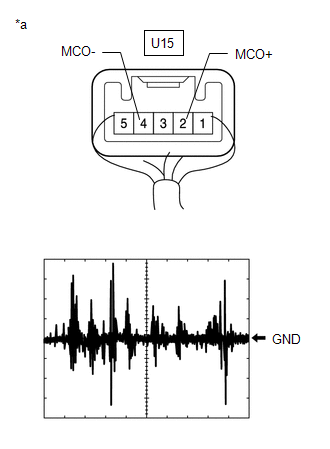
| *a | Component with harness connected (Telephone Microphone Assembly) |
(a) Check the output waveform.
(1) Remove the telephone microphone assembly with the connector(s) still connected.
(2) Connect an oscilloscope to terminal U15-2 (MCO+) and U15-4 (MCO-).
(3) Turn the engine switch on (ACC).
(4) Sound is input to the telephone microphone assembly when the user is closer than 125 mm from the telephone microphone assembly sound holes in the roof headlining holder cover.
(5) Check the signal waveform according to the condition(s) in the table below.
| Item | Condition |
|---|---|
| Measurement terminal | U15-2 (MCO+) - U15-4 (MCO-) |
| Tool setting | 50 mV/DIV., 500 ms/DIV. |
| Vehicle condition |
|
OK:
The waveform is similar to that shown in the illustration.
HINT:
The oscilloscope waveform shown in the illustration is an example for reference only.
| OK | | REPLACE RADIO RECEIVER ASSEMBLY |
| NG | | REPLACE TELEPHONE MICROPHONE ASSEMBLY |
 Start Up Signal Circuit between Radio Receiver Assembly and Navigation ECU
DESCRIPTION This circuit includes the navigation ECU and radio receiver assembly. WIRING DIAGRAM PROCEDURE 1. CHECK HARNESS AND CONNECTOR (RADIO RECEIVER ASSEMBLY - NAVIGATION ECU) (a) Disco ...
 Visual Mute Signal Circuit between Radio Receiver and Multi-display
DESCRIPTION The radio receiver assembly sends a visual mute signal to the multi-display assembly. As a result, a black screen is displayed when the screen changes so that noise and distorted images ar ...
Other materials:
Lexus RX (RX 350L, RX450h) 2016-2026 Repair Manual > Lighting System (w/o Automatic Headlight Beam Level Control System): System Diagram
SYSTEM DIAGRAM HEADLIGHT ASSEMBLY CIRCUIT ...
Lexus RX (RX 350L, RX450h) 2016-2026 Repair Manual > Air Cooled Oil Cooler: Components
COMPONENTS ILLUSTRATION *1 OIL COOLER ASSEMBLY *2 TRANSMISSION OIL COOLER AIR DUCT *3 OIL COOLER BRACKET *4 OUTLET NO. 1 OIL COOLER HOSE *5 TRANSMISSION OIL COOLER HOSE - - N*m (kgf*cm, ft.*lbf): Specified torque - - ...
Lexus RX (RX 350L, RX450h) 2016-{YEAR} Owners Manual
- For your information
- Pictorial index
- For safety and security
- Instrument cluster
- Operation of each component
- Driving
- Lexus Display Audio system
- Interior features
- Maintenance and care
- When trouble arises
- Vehicle specifications
- For owners
Lexus RX (RX 350L, RX450h) 2016-{YEAR} Repair Manual

0.0113