Lexus RX (RX 350L, RX450h) 2016-2026 Repair Manual: Reverse Signal Circuit between Radio Receiver Assembly and Navigation ECU
DESCRIPTION
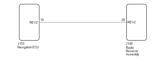
This circuit includes the navigation ECU and radio receiver assembly.
WIRING DIAGRAM
PROCEDURE
| 1. | CHECK HARNESS AND CONNECTOR (RADIO RECEIVER ASSEMBLY - NAVIGATION ECU) |
(a) Disconnect the J149 radio receiver assembly connector.
(b) Disconnect the J153 navigation ECU connector.
(c) Measure the resistance according to the value(s) in the table below.
Standard Resistance:
| Tester Connection | Condition | Specified Condition |
|---|---|---|
| J149-28 (REV2) - J153-19 (REV2) | Always | Below 1 Ω |
| J149-28 (REV2) or J153-19 (REV2) - Body ground | Always | 10 kΩ or higher |
| OK |  | PROCEED TO NEXT SUSPECTED AREA SHOWN IN PROBLEM SYMPTOMS TABLE |
| NG | | REPAIR OR REPLACE HARNESS OR CONNECTOR |
 Vehicle Speed Signal Circuit between Stereo Component Amplifier and Combination Meter
DESCRIPTION The stereo component amplifier assembly receives a vehicle speed signal from the combination meter assembly to control the ASL function. HINT:
A voltage of 12 V or 5 V is output from ea ...
 Start Up Signal Circuit between Radio Receiver Assembly and Navigation ECU
DESCRIPTION This circuit includes the navigation ECU and radio receiver assembly. WIRING DIAGRAM PROCEDURE 1. CHECK HARNESS AND CONNECTOR (RADIO RECEIVER ASSEMBLY - NAVIGATION ECU) (a) Disco ...
Other materials:
Lexus RX (RX 350L, RX450h) 2016-2026 Repair Manual > Heated Steering Wheel System: Fail-safe Chart
FAIL-SAFE CHART MALFUNCTION DETECTION (a) Operation when malfunction is detected Content Operation Heater failure Overcurrent detection of drive element Heater output off Overheating detection of drive element Heater output off Power failure Low-voltage detection Heater ou ...
Lexus RX (RX 350L, RX450h) 2016-2026 Repair Manual > Compressor: Inspection
INSPECTION PROCEDURE 1. INSPECT COOLER COMPRESSOR ASSEMBLY (A/C LOCK SENSOR) (a) Measure the resistance according to the value(s) in the table below. Standard Resistance: Tester Connection Condition Specified Condition 1 (SSR+) - 2 (SSR-) 20°C (68°F) 160 to 320 Ω If the resi ...
Lexus RX (RX 350L, RX450h) 2016-{YEAR} Owners Manual
- For your information
- Pictorial index
- For safety and security
- Instrument cluster
- Operation of each component
- Driving
- Lexus Display Audio system
- Interior features
- Maintenance and care
- When trouble arises
- Vehicle specifications
- For owners
Lexus RX (RX 350L, RX450h) 2016-{YEAR} Repair Manual

0.0091