Lexus RX (RX 350L, RX450h) 2016-2026 Repair Manual: Inspection
INSPECTION
PROCEDURE
1. INSPECT TIE ROD ASSEMBLY LH
| (a) Secure the tie rod assembly LH in a vise between aluminum plates. NOTICE: Do not overtighten the vise. |
|
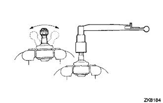
(b) Install the nut to the stud bolt.
(c) Flip the ball joint back and forth 5 times.
(d) Using a torque wrench and the nut, turn the stud bolt continuously at a rate of 2 to 4 seconds per turn, and check the turning torque on the 5th turn.
Standard Turning Torque:
0.49 to 3.43 N*m (5 to 34 kgf*cm, 5 to 30 in.*lbf)
If the turning torque is not within the specified range, replace the tie rod assembly LH with a new one.
(e) Check that the ball joint dust cover is not cracked and that there is no grease on it.
If the ball joint dust cover is cracked or there is grease on it, replace the tie rod assembly LH with a new one.
2. INSPECT TIE ROD ASSEMBLY RH
HINT:
Perform the same procedure as for the LH side.
3. INSPECT TOTAL PRELOAD
NOTICE:
Inspect the total preload in a no-load condition by removing the tie rod assemblies RH and LH, and steering rack boots.
| (a) Install SST to the pinion shaft and turn it left and right 5 times or more. SST: 09616-00020 |
|
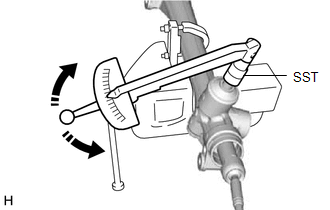
(b) Using a torque wrench and SST, turn the pinion shaft continuously at a rate of 4 to 6 seconds per turn to inspect the total preload of the steering gear assembly.
Standard Preload:
1.5 to 2.2 N*m (16 to 22 kgf*cm, 14 to 19 in.*lbf)
NOTICE:
Inspect the total preload around the steering rack center position.
If the total preload is not within the specified range, replace the steering gear assembly with a new one.
 Disassembly
DISASSEMBLY PROCEDURE 1. REMOVE STEERING RACK BOOT CLIP (for LH Side) (a) Using pliers, remove the steering rack boot clip. 2. REMOVE STEERING RACK BOOT CLIP (for RH Side) HINT: Perform the same proce ...
 Installation
INSTALLATION PROCEDURE 1. INSTALL TIE ROD ASSEMBLY LH (a) Install the lock nut and tie rod assembly LH to the steering gear assembly until the matchmarks are aligned. HINT: After adjusting the toe- ...
Other materials:
Lexus RX (RX 350L, RX450h) 2016-2026 Repair Manual > Transfer Case Front Oil Seal (for Lh Side): Replacement
REPLACEMENT CAUTION / NOTICE / HINT The necessary procedures (adjustment, calibration, initialization or registration) that must be performed after parts are removed and installed, or replaced during transfer case oil seal removal/installation are shown below. Necessary Procedure After Parts Removed ...
Lexus RX (RX 350L, RX450h) 2016-2026 Repair Manual > Charging System: How To Proceed With Troubleshooting
CAUTION / NOTICE / HINT HINT: *: Use the Techstream. PROCEDURE 1. VEHICLE BROUGHT TO WORKSHOP
NEXT 2. CUSTOMER PROBLEM ANALYSIS HINT:
In troubleshooting, confirm that the problem symptoms have been accurately identified. Preconceptions should be discarded in ord ...
Lexus RX (RX 350L, RX450h) 2016-{YEAR} Owners Manual
- For your information
- Pictorial index
- For safety and security
- Instrument cluster
- Operation of each component
- Driving
- Lexus Display Audio system
- Interior features
- Maintenance and care
- When trouble arises
- Vehicle specifications
- For owners
Lexus RX (RX 350L, RX450h) 2016-{YEAR} Repair Manual

0.0115