Lexus RX (RX 350L, RX450h) 2016-2026 Repair Manual: Installation
INSTALLATION
PROCEDURE
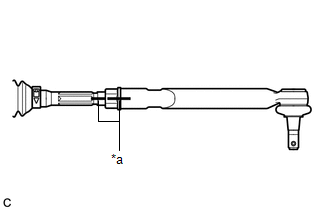
1. INSTALL TIE ROD ASSEMBLY LH
| (a) Install the lock nut and tie rod assembly LH to the steering gear assembly until the matchmarks are aligned. HINT: After adjusting the toe-in, tighten the lock nut. |
|
2. INSTALL TIE ROD ASSEMBLY RH
HINT:
Perform the same procedure as for the LH side.
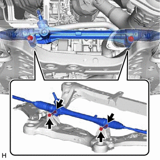
3. INSTALL STEERING LINK ASSEMBLY
| (a) Install the steering link assembly to the front frame assembly with the 2 bolts and 2 nuts. Torque: 70 N·m {714 kgf·cm, 52 ft·lbf} NOTICE:
|
|
4. INSTALL FRONT STABILIZER BAR
(a) Install the front stabilizer bar to the front frame assembly.
5. INSTALL FRONT NO. 2 STABILIZER BRACKET LH
(a) Install the front No. 2 stabilizer bracket LH to the front frame assembly.
6. INSTALL FRONT NO. 2 STABILIZER BRACKET RH
HINT:
Perform the same procedure as for the LH side.
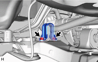
7. INSTALL FRONT NO. 1 STABILIZER BRACKET LH
| (a) Install the front No. 1 stabilizer bracket LH to the front frame assembly with the 2 bolts. Torque: 93 N·m {948 kgf·cm, 69 ft·lbf} |
|
8. INSTALL FRONT NO. 1 STABILIZER BRACKET RH
HINT:
Perform the same procedure as for the LH side.
9. CONNECT TIE ROD ASSEMBLY LH
| (a) Connect the tie rod assembly LH to the steering knuckle LH with the nut. Torque: 49 N·m {500 kgf·cm, 36 ft·lbf} NOTICE:
|
|
(b) Install a new cotter pin.
10. CONNECT TIE ROD ASSEMBLY RH
HINT:
Perform the same procedure as for the LH side.
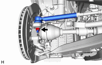
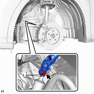
11. CONNECT FRONT STABILIZER LINK ASSEMBLY LH
| (a) Install the front stabilizer link assembly LH to the front stabilizer bar with the nut. Torque: 76 N·m {775 kgf·cm, 56 ft·lbf} HINT: If the ball joint turns together with the nut, use a 6 mm hexagon wrench to hold the stud bolt. |
|
12. CONNECT FRONT STABILIZER LINK ASSEMBLY RH
HINT:
Perform the same procedure as for the LH side.
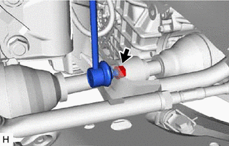
13. CONNECT STEERING INTERMEDIATE SHAFT ASSEMBLY
| (a) Align the matchmarks on the steering intermediate shaft assembly and steering link assembly. |
|
(b) Connect the steering intermediate shaft assembly to the steering link assembly.
(c) Install a new bolt.
Torque:
64 N·m {653 kgf·cm, 47 ft·lbf}
14. INSTALL NO. 2 ENGINE UNDER COVER
Click here .gif)
15. INSTALL FRONT WHEELS
Click here
16. INSPECT AND ADJUST FRONT WHEEL ALIGNMENT
Click here
 Inspection
INSPECTION PROCEDURE 1. INSPECT TIE ROD ASSEMBLY LH (a) Secure the tie rod assembly LH in a vise between aluminum plates. NOTICE: Do not overtighten the vise. (b) Install the nut to the ...
 Reassembly
REASSEMBLY PROCEDURE 1. INSTALL NO. 2 STEERING RACK BOOT (a) Apply lithium soap base glycol grease to the inside of the small opening of a new No. 2 steering rack boot. Lithium Soap Base Glycol ...
Other materials:
Lexus RX (RX 350L, RX450h) 2016-2026 Repair Manual > Vehicle Stability Control System: Brake System Control Module "A" Internal Electronic Failure (C059749,...,C13C91C)
DESCRIPTION The solenoid relay and solenoid valves are built into the brake actuator assembly. The solenoid valves control the brake fluid pressure at each wheel cylinder. When this DTC is stored, the fail-safe function operates and the solenoid relay is turned off to prevent the solenoid valves fro ...
Lexus RX (RX 350L, RX450h) 2016-2026 Repair Manual > Lane Control System: Lost Communication with ECM/PCM "A" Missing Message (U010087,U012587,U012687,U012987,U013187,U015587)
DESCRIPTION When a communication malfunction is detected between the forward recognition camera and an ECU or sensor, a DTC is stored. DTC No. Detection Item DTC Detection Condition Trouble Area U010087 Lost Communication with ECM/PCM "A" Missing Message 2 seconds after the engine s ...
Lexus RX (RX 350L, RX450h) 2016-{YEAR} Owners Manual
- For your information
- Pictorial index
- For safety and security
- Instrument cluster
- Operation of each component
- Driving
- Lexus Display Audio system
- Interior features
- Maintenance and care
- When trouble arises
- Vehicle specifications
- For owners
Lexus RX (RX 350L, RX450h) 2016-{YEAR} Repair Manual

0.0106