Lexus RX (RX 350L, RX450h) 2016-2026 Repair Manual: Front Camera Module Communication Stop Mode
DESCRIPTION
| Detection Item | Symptom | Trouble Area |
|---|---|---|
| Front Camera Module Communication Stop Mode | Either condition is met:
|
|
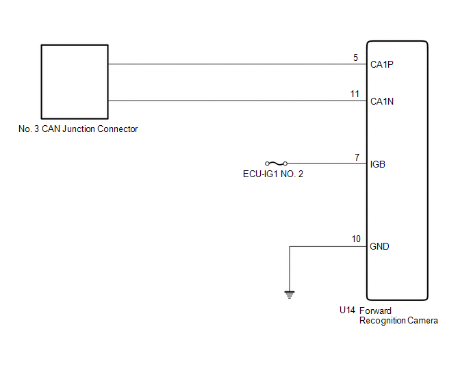
WIRING DIAGRAM
CAUTION / NOTICE / HINT
NOTICE:
- Before measuring the resistance of the CAN bus, turn the engine switch off and leave the vehicle for 1 minute or more without operating the key or any switches, or opening or closing the doors. After that, disconnect the cable from the negative (-) battery terminal and leave the vehicle for 1 minute or more before measuring the resistance.
-
After turning the engine switch off, waiting time may be required before disconnecting the cable from the negative (-) battery terminal. Therefore, make sure to read the disconnecting the cable from the negative (-) battery terminal notices before proceeding with work.
Click here
.gif)
-
Because the order of diagnosis is important to allow correct diagnosis, make sure to begin troubleshooting using How to Proceed with Troubleshooting when CAN communication system related DTCs are output.
Click here
- After performing repairs, perform the DTC check procedure and confirm that the DTCs are not output again.
- DTC check procedure: Drive the vehicle at a speed of 5 km/h (3 mph) or more for 52 seconds or more.
-
After the repair, perform the CAN bus check and check that all the ECUs and sensors connected to the CAN communication system are displayed.
Click here
- Inspect the fuses for circuits related to this system before performing the following procedure.
HINT:
- Operating the engine switch, any other switches or a door triggers related ECU and sensor communication on the CAN. This communication will cause the resistance value to change.
- Even after DTCs are cleared, if a DTC is stored again after driving the vehicle for a while, the malfunction may be occurring due to vibration of the vehicle. In such a case, wiggling the ECUs or wire harness while performing the inspection below may help determine the cause of the malfunction.
PROCEDURE
| 1. | CHECK FOR OPEN IN CAN BUS LINES (FORWARD RECOGNITION CAMERA BRANCH LINE) |
(a) Disconnect the cable from the negative (-) battery terminal.
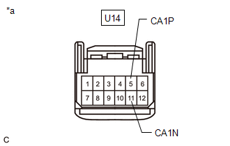
| (b) Disconnect the U14 forward recognition camera connector. |
|
(c) Measure the resistance according to the value(s) in the table below.
Standard Resistance:
| Tester Connection | Condition | Specified Condition |
|---|---|---|
| U14-5 (CA1P) - U14-11 (CA1N) | Cable disconnected from negative (-) battery terminal | 54 to 69 Ω |
| NG | .gif) | REPAIR OR REPLACE CAN BRANCH LINES OR CONNECTOR (FORWARD RECOGNITION CAMERA) |
|
.gif)
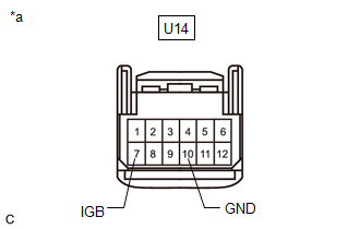
| 2. | CHECK HARNESS AND CONNECTOR (POWER SOURCE CIRCUIT) |
| (a) Measure the resistance according to the value(s) in the table below. Standard Resistance:
|
|
(b) Reconnect the cable to the negative (-) battery terminal.
(c) Measure the voltage according to the value(s) in the table below.
Standard Voltage:
| Tester Connection | Condition | Specified Condition |
|---|---|---|
| U14-7 (IGB) - Body ground | Engine switch on (IG) | 11 to 14 V |
| OK | | REPLACE FORWARD RECOGNITION CAMERA |
| NG | | REPAIR OR REPLACE HARNESS OR CONNECTOR (POWER SOURCE CIRCUIT) |
 Open in One Side of Bus 5 Branch Line
DESCRIPTION If an ECU or sensor is not displayed on the CAN Bus Check screen of the Techstream and some ECUs and sensors repeatedly appear and disappear from the screen when the CAN main bus lines are ...
 Tire Pressure Monitor ECU Communication Stop Mode
DESCRIPTION Detection Item Symptom Trouble Area Tire Pressure Monitor ECU Communication Stop Mode Either condition is met:
"Tire Pressure" is not displayed on the CAN Bus Check screen ...
Other materials:
Lexus RX (RX 350L, RX450h) 2016-2026 Repair Manual > Refrigerant (for Hfo-1234yf(r1234yf)): Precaution
PRECAUTION PRECAUTIONS FOR REFRIGERANT HFO-1234yf (R1234yf) (a) Compatibility (1) The parts used in the refrigerant cycle, the compressor oil, etc. of an HFO-1234yf (R1234yf) system are not compatible with a conventional HFC-134a (R134a) system. (b) HFO-1234yf (R1234yf) Refrigerant (1) Always use HF ...
Lexus RX (RX 350L, RX450h) 2016-2026 Repair Manual > Sfi System: Throttle / Pedal Position Sensor / Switch "A" Circuit Short to Ground (P012011,P012015,P01201C,P022011,P022015,P21352B)
DESCRIPTION HINT: These DTCs relate to the throttle position sensor. The throttle position sensor is mounted on the throttle body with motor assembly and detects the opening angle of the throttle valve. This sensor is a non-contact type sensor. It uses Hall-effect elements in order to yield accurate ...
Lexus RX (RX 350L, RX450h) 2016-{YEAR} Owners Manual
- For your information
- Pictorial index
- For safety and security
- Instrument cluster
- Operation of each component
- Driving
- Lexus Display Audio system
- Interior features
- Maintenance and care
- When trouble arises
- Vehicle specifications
- For owners
Lexus RX (RX 350L, RX450h) 2016-{YEAR} Repair Manual

0.0106