Lexus RX (RX 350L, RX450h) 2016-2026 Repair Manual: Communication Malfunction between ECUs Connected by LIN (B2785)
DESCRIPTION
If the certification ECU (smart key ECU assembly) detects a communication error with an ECU connected to the certification bus lines for 7 sedonds or more, DTC B2785 will be stored.
| DTC No. | Detection Item | DTC Detection Condition | Trouble Area |
|---|---|---|---|
| B2785 | Communication Malfunction between ECUs Connected by LIN |
|
|
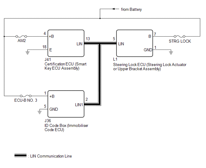
WIRING DIAGRAM
CAUTION / NOTICE / HINT
NOTICE:
- Inspect the fuses for circuits related to this system before performing the following procedure.
-
If the certification ECU (smart key ECU assembly), ID code box (immobiliser code ECU) and steering lock ECU (steering lock actuator or upper bracket assembly) is replaced, refer to Registration.
Click here
.gif)
-
Before performing the inspection, check that DTC B2786, B2789 or B278C is not output.
Click here
- When using the Techstream with the engine switch off, connect the Techstream to the DLC3 and turn a courtesy light switch on and off at intervals of 1.5 seconds or less until communication between the Techstream and the vehicle begins. Then select Model Code "KEY REGIST" under manual mode and enter the following menus: Body Electrical / Smart Access(CAN). While using the Techstream, periodically turn a courtesy light switch on and off at intervals of 1.5 seconds or less to maintain communication between the Techstream and the vehicle.
PROCEDURE
| 1. | CHECK HARNESS AND CONNECTOR (CERTIFICATION ECU (SMART KEY ECU ASSEMBLY) - EACH ECU) |
(a) Disconnect the J41 certification ECU (smart key ECU assembly) connector.
(b) Disconnect the L1 steering lock ECU (steering lock actuator or upper bracket assembly) connector.
(c) Disconnect the J36 ID code box (immobiliser code ECU) connector.
(d) Measure the resistance according to the value(s) in the table below.
NOTICE:
Make sure that each ECU is in sleep mode before performing the inspection. To enter sleep mode, turn the engine switch from on (IG) to off and wait for 180 seconds or more without operating any switches.
Standard Resistance:
| Tester Connection | Condition | Specified Condition |
|---|---|---|
| J41-13 (LIN) - J36-2 (LIN1) | Engine switch off | Below 1 Ω |
| J41-13 (LIN) - L1-5 (LIN) | Engine switch off | Below 1 Ω |
| J41-13 (LIN), L1-5 (LIN) or J36-2 (LIN1) - Body ground | Engine switch off | 10 kΩ or higher |
| NG | .gif) | REPAIR OR REPLACE HARNESS OR CONNECTOR |
|
.gif)
| 2. | CHECK FOR DTC (STEERING LOCK ECU (STEERING LOCK ACTUATOR OR UPPER BRACKET ASSEMBLY)) |
(a) Reconnect the J41 certification ECU (smart key ECU assembly) connector.
(b) Reconnect the J36 ID code box (immobiliser code ECU) connector.
(c) Clear the DTCs.
Click here
(d) Recheck for DTCs.
Body Electrical > Smart Access > Trouble Codes| Result | Proceed to |
|---|---|
| DTC B2785 is output | A |
| DTC B2785 is not output | B |
| B | | REPLACE STEERING LOCK ECU (STEERING LOCK ACTUATOR OR UPPER BRACKET ASSEMBLY) |
|
| 3. | CHECK FOR DTC (ID CODE BOX (IMMOBILISER CODE ECU)) |
(a) Reconnect the L1 steering lock ECU (steering lock actuator or upper bracket assembly) connector.
(b) Disconnect the J36 ID code box (immobiliser code ECU) connector.
(c) Clear the DTCs.
Click here
(d) Recheck for DTCs.
Body Electrical > Smart Access > Trouble Codes| Result | Proceed to |
|---|---|
| DTC B2785 is output | A |
| DTC B2785 is not output | B |
| A | | REPLACE CERTIFICATION ECU (SMART KEY ECU ASSEMBLY) |
| B | | REPLACE ID CODE BOX (IMMOBILISER CODE ECU) |
 Lost Communication with Sliding Sunshade ECU (B2329)
DESCRIPTION This DTC is stored when LIN communication between the roof sunshade ECU (sliding roof drive gear assembly) and main body ECU (multiplex network body ECU) stops for 10 seconds or more. D ...
 No Response from Steering Lock ECU (B2786)
DESCRIPTION This DTC is stored when LIN communication between the certification ECU (smart key ECU assembly) and steering lock ECU (steering lock actuator or upper bracket assembly) stops for 10 secon ...
Other materials:
Lexus RX (RX 350L, RX450h) 2016-2026 Repair Manual > Trip Switch: Installation
INSTALLATION PROCEDURE 1. INSTALL TRIP SWITCH (a) Engage the 2 claws as shown in the illustration to install the trip switch. Install in this Direction 2. INSTALL INSTRUMENT CLUSTER FINISH PANEL SUB-ASSEMBLY Click here 3. INSTALL LOWER INSTRUMENT FINISH PANEL SUB Click here 4. INSTAL ...
Lexus RX (RX 350L, RX450h) 2016-2026 Repair Manual > Safety Connect System: Backup Battery Internal Electronic Failure (B15CC49)
DESCRIPTION This DTC is set when the DCM (telematics transceiver) detects one of the following:
The mobilephone battery voltage drops or the mobilephone battery malfunctions.
The mobilephone battery temperature is (temporarily) high.
DTC No. Detection Item DTC Detection Condition Tr ...
Lexus RX (RX 350L, RX450h) 2016-{YEAR} Owners Manual
- For your information
- Pictorial index
- For safety and security
- Instrument cluster
- Operation of each component
- Driving
- Lexus Display Audio system
- Interior features
- Maintenance and care
- When trouble arises
- Vehicle specifications
- For owners
Lexus RX (RX 350L, RX450h) 2016-{YEAR} Repair Manual

0.0111