Lexus RX (RX 350L, RX450h) 2016-2026 Repair Manual: Lost Communication with Sliding Sunshade ECU (B2329)
DESCRIPTION
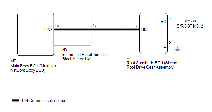
This DTC is stored when LIN communication between the roof sunshade ECU (sliding roof drive gear assembly) and main body ECU (multiplex network body ECU) stops for 10 seconds or more.
| DTC No. | Detection Item | DTC Detection Condition | Trouble Area |
|---|---|---|---|
| B2329 | Lost Communication with Sliding Sunshade ECU | No communication between roof sunshade ECU (sliding roof drive gear assembly) and main body ECU (multiplex network body ECU) for 10 seconds or more. |
|
WIRING DIAGRAM
CAUTION / NOTICE / HINT
NOTICE:
- Inspect the fuses for circuits related to this system before performing the following procedure.
-
Before replacing the main body ECU (multiplex network body ECU), refer to Registration.
Click here
.gif)
-
When the roof sunshade ECU (sliding roof drive gear sub-assembly) is replaced or removed and reinstalled, it is necessary to perform initialization.
Click here
PROCEDURE
| 1. | INSPECT INSTRUMENT PANEL JUNCTION BLOCK ASSEMBLY |
(a) Remove the instrument panel junction block assembly.
Click here
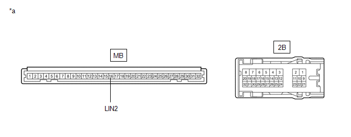
| *a | Component without harness connected (Instrument Panel Junction Block Assembly) | - | - |
(b) Remove the main body ECU (multiplex network body ECU) from the instrument panel junction block assembly.
(c) Measure the resistance according to the value(s) in the table below.
HINT:
This inspection is to check the LIN communication line in the instrument panel junction block assembly that connects the wire harness to the built-in main body ECU (multiplex network body ECU).
Standard Resistance:
| Tester Connection | Condition | Specified Condition |
|---|---|---|
| 2B-17 - MB-16 (LIN2) | Always | Below 1 Ω |
| NG | .gif) | REPLACE INSTRUMENT PANEL JUNCTION BLOCK ASSEMBLY |
|
.gif)
| 2. | CHECK HARNESS AND CONNECTOR (INSTRUMENT PANEL JUNCTION BLOCK ASSEMBLY - ROOF SUNSHADE ECU (SLIDING ROOF DRIVE GEAR ASSEMBLY)) |
(a) Disconnect the w1 roof sunshade ECU (sliding roof drive gear assembly) connector.
(b) Measure the resistance according to the value(s) in the table below.
NOTICE:
Make sure that each ECU is in sleep mode before performing the inspection. To enter sleep mode, turn the engine switch from ON to off and wait for 180 seconds or more without operating any switches.
Standard Resistance:
| Tester Connection | Condition | Specified Condition |
|---|---|---|
| 2B-17 -w1-7 (LIN) | Engine switch off | Below 1 Ω |
| w1-7 (LIN) or 2B-17 - Body ground | Engine switch off | 10 kΩ or higher |
| NG | | REPAIR OR REPLACE HARNESS OR CONNECTOR |
|
| 3. | CHECK HARNESS AND CONNECTOR (ROOF SUNSHADE ECU (SLIDING ROOF DRIVE GEAR ASSEMBLY) - BATTERY, BODY GROUND) |
(a) Measure the voltage according to the value(s) in the table below.
Standard Voltage:
| Tester Connection | Condition | Specified Condition |
|---|---|---|
| w1-1 (+B) - w1-2 (E) | Always | 11 to 14 V |
(b) Measure the resistance according to the value(s) in the table below.
Standard Resistance:
| Tester Connection | Condition | Specified Condition |
|---|---|---|
| w1-2 (E) - Body ground | Always | Below 1 Ω |
| NG | | REPAIR OR REPLACE HARNESS OR CONNECTOR |
|
| 4. | REPLACE ROOF SUNSHADE ECU (SLIDING ROOF DRIVE GEAR ASSEMBLY) |
(a) Replace the roof sunshade ECU (sliding roof drive gear assembly).
Click here
|
| 5. | CHECK FOR DTC |
(a) Clear the DTCs.
Click here
(b) Recheck for DTCs.
Body Electrical > Main Body > Trouble CodesOK:
DTC B2329 is not output.
| OK | | END (ROOF SUNSHADE ECU (SLIDING ROOF DRIVE GEAR ASSEMBLY) WAS DEFECTIVE) |
| NG | | REPLACE MAIN BODY ECU (MULTIPLEX NETWORK BODY ECU) |
 LIN Communication Bus Malfunction (B2325)
DESCRIPTION If the main body ECU (multiplex network body ECU) detects a communication error with an ECU connected to the door bus lines for 7 seconds or more, DTC B2325 will be stored. DTC No. De ...
 Communication Malfunction between ECUs Connected by LIN (B2785)
DESCRIPTION If the certification ECU (smart key ECU assembly) detects a communication error with an ECU connected to the certification bus lines for 7 sedonds or more, DTC B2785 will be stored. DTC ...
Other materials:
Lexus RX (RX 350L, RX450h) 2016-2026 Repair Manual > Front Console Box: Removal
REMOVAL PROCEDURE 1. REMOVE REAR CONSOLE UPPER PANEL (a) Disengage the 3 clips and 2 claws in the direction indicated by the arrow (1). Place Hand Here Remove in this Direction (1) Remove in this Direction (2) (b) Pull the rear console upper panel in the direction indicated b ...
Lexus RX (RX 350L, RX450h) 2016-2026 Repair Manual > Sfi System: Initialization
INITIALIZATION Inspection After Repair Perform Learning Value Reset and Idle Learning after replacing or servicing parts related to engine operation. Details on procedures required are indicated by an asterisk and a number, and are explained in detail following the table. Part Replaced Engine O ...
Lexus RX (RX 350L, RX450h) 2016-{YEAR} Owners Manual
- For your information
- Pictorial index
- For safety and security
- Instrument cluster
- Operation of each component
- Driving
- Lexus Display Audio system
- Interior features
- Maintenance and care
- When trouble arises
- Vehicle specifications
- For owners
Lexus RX (RX 350L, RX450h) 2016-{YEAR} Repair Manual

0.0109