Lexus RX (RX 350L, RX450h) 2016-2026 Repair Manual: Torque Sensor1 (C1511-C1514,C1517)
DESCRIPTION
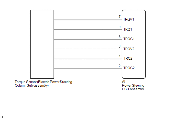
The torque sensor converts the rotational torque received from the steering wheel into electric signals and sends them to the power steering ECU assembly.
| DTC No. | Detection Item | DTC Detection Condition | Trouble Area | Warning Indicate | Return-to-normal Condition | Note |
|---|---|---|---|---|---|---|
| C1511 | Torque Sensor1 | Torque sensor malfunction |
| EPS warning light: Comes on | The ECU judges the system has returned to normal or the power switch is turned on (IG) again | - |
| C1512 | Torque Sensor2 | Torque sensor malfunction |
| EPS warning light: Comes on | The ECU judges the system has returned to normal or the power switch is turned on (IG) again | - |
| C1513 | Torque Sensor Deviation Excessive | Torque sensor malfunction |
| EPS warning light: Comes on | The ECU judges the system has returned to normal or the power switch is turned on (IG) again | - |
| C1514 | Torque Sensor Power Supply Voltage | Torque sensor malfunction |
| EPS warning light: Comes on | Engine switch on (IG) again | - |
| C1517 | Torque Hold | Torque sensor malfunction |
| EPS warning light: Comes on | Engine switch on (IG) again | - |
WIRING DIAGRAM
CAUTION / NOTICE / HINT
NOTICE:
-
If the electric power steering column sub-assembly has been replaced, perform torque sensor zero point calibration.
Click here
.gif)
-
If the power steering ECU assembly has been replaced, perform assist map writing and torque sensor zero point calibration.
Click here
PROCEDURE
| 1. | CHECK CONNECTOR CONNECTION CONDITION |
(a) Check the connection condition of the torque sensor connector.
OK:
Torque sensor connector is securely connected to the power steering ECU assembly.
| NG |  | CONNECT CONNECTOR |
|

| 2. | CHECK POWER STEERING ECU ASSEMBLY (TRQV VOLTAGE) |
| (a) Turn the engine switch to on (IG). |
|
(b) Measure the voltage according to the value(s) in the table below.
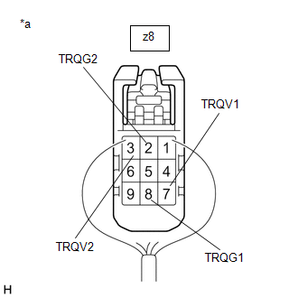
Standard Voltage:
| Tester Connection | Condition | Specified Condition |
|---|---|---|
| z8-7 (TRQV1) - z8-8 (TRQG1) | Engine switch on (IG) | 4.5 to 5.5 V |
| z8-3 (TRQV2) - z8-2 (TRQG2) | Engine switch on (IG) | 4.5 to 5.5 V |
| NG | | REPLACE POWER STEERING ECU ASSEMBLY |
|
| 3. | CHECK POWER STEERING ECU ASSEMBLY (TRQ1, TRQ2 VOLTAGE) |
| (a) Start the engine. |
|
(b) Measure the voltage according to the value(s) in the table below.
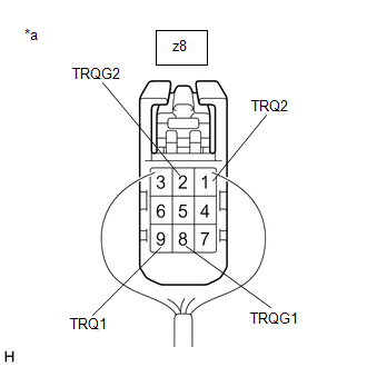
Standard Voltage:
| Tester Connection | Condition | Specified Condition |
|---|---|---|
| z8-9 (TRQ1) - z8-8 (TRQG1) | Engine running and steering wheel not being turned (without load) | 2.3 to 2.7 V |
| Engine running and steering wheel being turned to the right with vehicle stopped | 2.5 to 3.8 V | |
| Engine running and steering wheel being turned to the left with vehicle stopped | 1.2 to 2.5 V | |
| z8-1 (TRQ2) - z8-2 (TRQG2) | Engine running and steering wheel not being turned (without load) | 2.3 to 2.7 V |
| Engine running and steering wheel being turned to the right with vehicle stopped | 1.2 to 2.5 V | |
| Engine running and steering wheel being turned to the left with vehicle stopped | 2.5 to 3.8 V |
(c) Under each condition, measure the voltage at terminals TRQ1 and TRQ2, and calculate the sum.
Standard Voltage:
| Tester Connection | Condition | Specified Condition |
|---|---|---|
| Sum of voltage between z8-9 (TRQ1) and z8-8 (TRQG1) and voltage between z8-1 (TRQ2) and z8-2 (TRQG2) | Engine running and steering wheel not being turned (without load) | Between 4.75 V and 5.25 V |
| Engine running and steering wheel being turned to the right with vehicle stopped | ||
| Engine running and steering wheel being turned to the left with vehicle stopped |
| OK | | REPLACE POWER STEERING ECU ASSEMBLY |
| NG | | REPLACE ELECTRIC POWER STEERING COLUMN SUB-ASSEMBLY |

 Torque Sensor Zero Point Adjustment Undone (C1515)
DESCRIPTION This DTC does not indicate a malfunction. The power steering ECU assembly stores this DTC when it determines that torque sensor zero point calibration has not been performed. DTC No. ...
Other materials:
Lexus RX (RX 350L, RX450h) 2016-2026 Repair Manual > Automatic Transaxle Assembly: Components
COMPONENTS ILLUSTRATION *1 OUTER COWL TOP PANEL SUB-ASSEMBLY - - N*m (kgf*cm, ft.*lbf): Specified torque - - ILLUSTRATION *1 FRONT WHEEL OPENING EXTENSION PAD LH *2 NO. 3 ENGINE UNDER COVER *3 FRONT FENDER APRON SEAL LH - - ILLUSTRATION *1 FRONT L ...
Lexus RX (RX 350L, RX450h) 2016-2026 Repair Manual > Blind Spot Monitor System: Open in Outer Mirror Indicator(Master) (C1AB4)
DESCRIPTION This DTC is stored when the blind spot monitor sensor LH detects an open in the outer rear view mirror indicator LH. DTC No. Detection Item DTC Detection Condition Trouble Area C1AB4 Open in Outer Mirror Indicator(Master) Both of the following conditions are met:
The ...
Lexus RX (RX 350L, RX450h) 2016-{YEAR} Owners Manual
- For your information
- Pictorial index
- For safety and security
- Instrument cluster
- Operation of each component
- Driving
- Lexus Display Audio system
- Interior features
- Maintenance and care
- When trouble arises
- Vehicle specifications
- For owners
Lexus RX (RX 350L, RX450h) 2016-{YEAR} Repair Manual

0.0108