Lexus RX (RX 350L, RX450h) 2016-2026 Repair Manual: Drive Mode Select Switch Circuit
DESCRIPTION
The electronic throttle and the EPS character change by the operation of the drive mode select switch (combination switch assembly).
WIRING DIAGRAM
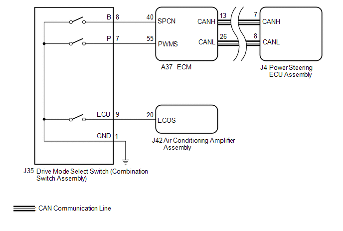
PROCEDURE
| 1. | CHECK THE PROBLEM SYMPTOMS |
(a) Check each symptom by checking the suspected areas in the table below.
| Result | Proceed to |
|---|---|
| SPORT, SPORT S/S+ mode or NORMAL mode is abnormal. | A |
| ECO mode is abnormal. | B |
| B | .gif) | GO TO AIR CONDITIONING SYSTEM |
|
.gif)
| 2. | CHECK CAN COMMUNICATION SYSTEM |
(a) Check for DTCs.
Click here .gif)
| Result | Proceed to |
|---|---|
| CAN communication system DTCs are not output. | A |
| CAN communication system DTCs are output. | B |
| B | | GO TO CAN COMMUNICATION SYSTEM |
|
| 3. | CHECK HARNESS AND CONNECTOR (DRIVE MODE SELECT SWITCH (COMBINATION SWITCH ASSEMBLY) - BODY GROUND) |
(a) Turn the engine switch off.
| (b) Disconnect the J35 drive mode select switch (combination switch assembly) connector. |
|
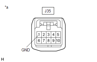
(c) Measure the resistance according to the value(s) in the table below.
Standard Resistance:
| Tester Connection | Condition | Specified Condition |
|---|---|---|
| J35-1 (GND) - Body ground | Always | Below 1 Ω |
| NG | | REPAIR OR REPLACE HARNESS OR CONNECTOR |
|
| 4. | INSPECT DRIVE MODE SELECT SWITCH (COMBINATION SWITCH ASSEMBLY) |
(a) Inspect drive mode select switch (combination switch assembly).
for U881E: Click here
for U881F: Click here
OK:
Drive mode select switch (combination switch assembly) is normal.
| NG | | REPLACE DRIVE MODE SELECT SWITCH (COMBINATION SWITCH ASSEMBLY) |
|
| 5. | CHECK HARNESS AND CONNECTOR (DRIVE MODE SELECT SWITCH (COMBINATION SWITCH ASSEMBLY) - ECM) |
(a) Reconnect the J35 drive mode select switch (combination switch assembly) connector.
| (b) Disconnect the A37 ECM connectors. |
|
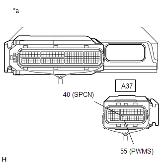
(c) Measure the resistance according to the value(s) in the table below.
Standard Resistance:
| Tester Connection | Condition | Specified Condition |
|---|---|---|
| A37-55 (PWMS) - Body ground | SPORT mode switch being turned and held | Below 50 Ω |
| A37-55 (PWMS) - Body ground | SPORT mode switch not turned | 10 kΩ or higher |
| A37-40 (SPCN) - Body ground | NORMAL mode switch being pushed and held | Below 50 Ω |
| A37-40 (SPCN) - Body ground | NORMAL mode switch not pushed | 10 kΩ or higher |
| OK | | REPLACE ECM |
| NG | | REPAIR OR REPLACE HARNESS OR CONNECTOR |
 Diagnostic Trouble Code Chart
DIAGNOSTIC TROUBLE CODE CHART Power Steering System DTC No. Detection Item DTC Detection Condition Warning Indicate Return-to-normal Condition Note Link C1511 Torque Sensor1 Tor ...
 Dtc Check / Clear
DTC CHECK / CLEAR CHECK DTCs (USING TECHSTREAM) (a) Turn the engine switch off. (b) Connect the Techstream to the DLC3. (c) Turn the engine switch on (IG). (d) Turn the Techstream on. (e) Enter the fo ...
Other materials:
Lexus RX (RX 350L, RX450h) 2016-2026 Repair Manual > Rear No. 1 Seat Inner Belt Assembly(for 60/40 Split Seat Type Rh Side): Components
COMPONENTS ILLUSTRATION *1 NO. 1 RECLINING ADJUSTER RELEASE HANDLE RH *2 REAR NO. 1 SEAT RECLINING ADJUSTER INSIDE COVER *3 REAR SEAT 3 POINT TYPE BELT ASSEMBLY RH *4 REAR SEAT COVER CAP RH *5 REAR SEAT LOCK CONTROL LEVER SUB-ASSEMBLY RH *6 SEPARATE TYPE REAR SEAT CUSHI ...
Lexus RX (RX 350L, RX450h) 2016-2026 Repair Manual > Combination Switch: Components
COMPONENTS ILLUSTRATION *1 CONSOLE PANEL SUB-ASSEMBLY *2 INSTRUMENT CLUSTER FINISH PANEL ORNAMENT *3 LOWER NO. 1 INSTRUMENT PANEL FINISH PANEL *4 LOWER NO. 2 INSTRUMENT PANEL FINISH PANEL *5 REAR CONSOLE UPPER PANEL *6 SHIFT LEVER KNOB SUB-ASSEMBLY ILLUSTRATION * ...
Lexus RX (RX 350L, RX450h) 2016-{YEAR} Owners Manual
- For your information
- Pictorial index
- For safety and security
- Instrument cluster
- Operation of each component
- Driving
- Lexus Display Audio system
- Interior features
- Maintenance and care
- When trouble arises
- Vehicle specifications
- For owners
Lexus RX (RX 350L, RX450h) 2016-{YEAR} Repair Manual

0.0135