Lexus RX (RX 350L, RX450h) 2016-2026 Repair Manual: Steering Wheel does not Heat Up When Heated Steering Wheel Switch is Pressed
DESCRIPTION
Click here .gif)
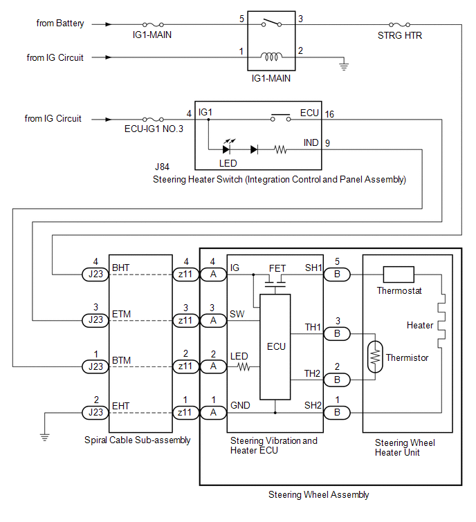
WIRING DIAGRAM
CAUTION / NOTICE / HINT
HINT:
- Inspect the fuses for circuits related to this system before performing the following inspection procedure.
- The steering wheel heater unit is built into the steering wheel assembly which cannot be disassembled. Therefore, when the steering wheel heater unit has a malfunction, replace the steering wheel assembly.
PROCEDURE
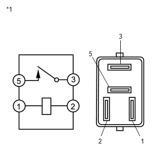
| 1. | CHECK IG1-MAIN RELAY |
(a) Remove the IG1-MAIN relay from the engine room relay block.
| (b) Measure the resistance according to the value(s) in the table below. Standard Resistance:
|
|
| NG | .gif) | REPLACE IG1-MAIN RELAY |
|
.gif)
| 2. | CHECK HARNESS AND CONNECTOR (IG1-MAIN RELAY POWER SOURCE) |
(a) Remove the IG1-MAIN relay from the engine room relay block.
(b) Measure the voltage according to the value(s) in the table below.
Standard Voltage:
| Tester Connection | Condition | Specified Condition |
|---|---|---|
| 5 (IG1-MAIN relay) - Body ground | Always | 11 to 14 V |
| 1 (IG1-MAIN relay) - Body ground | Engine switch on (IG) | 11 to 14 V |
(c) Measure the resistance according to the value(s) in the table below.
Standard Resistance:
| Tester Connection | Condition | Specified Condition |
|---|---|---|
| 2 (IG1-MAIN relay) - Body ground | Always | Below 1 Ω |
| NG | | REPAIR OR REPLACE HARNESS OR CONNECTOR |
|
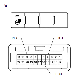
| 3. | CHECK HARNESS AND CONNECTOR (STEERING HEATER SWITCH (INTEGRATION CONTROL AND PANEL ASSEMBLY) POWER SOURCE) |
(a) Disconnect the J84 steering heater switch (integration control and panel assembly) connector.
(b) Measure the voltage according to the value(s) in the table below.
Standard Voltage:
| Tester Connection | Condition | Specified Condition |
|---|---|---|
| J84-4 (IG1) - Body ground | Engine switch on (IG) | 11 to 14 V |
| NG | | REPAIR OR REPLACE HARNESS OR CONNECTOR |
|
| 4. | CHECK STEERING HEATER SWITCH (INTEGRATION CONTROL AND PANEL ASSEMBLY) |
(a) Disconnect the J84 steering heater switch (integration control and panel assembly) connector.
| (b) Measure the voltage according to the value(s) in the table below. HINT: As the circuit has a diode, perform the measurement in diode test mode, and do not mistake the polarity. Standard Voltage:
|
|
(c) Measure the resistance according to the value(s) in the table below.
Standard Resistance:
| Tester Connection | Condition | Specified Condition |
|---|---|---|
| J84-4 (IG1) - J84-16 (ECU) | Steering heater switch (Integration control and panel assembly) is pushed | Below 1 Ω |
| Steering heater switch (Integration control and panel assembly) is not pushed | 10 kΩ or higher |
| NG | | REPLACE STEERING HEATER SWITCH (INTEGRATION CONTROL AND PANEL ASSEMBLY) |
|
| 5. | CHECK HARNESS AND CONNECTOR (IG1-MAIN RELAY - SPIRAL CABLE SUB-ASSEMBLY) |
(a) Remove the IG1-MAIN relay from the engine room relay block.
(b) Disconnect the J23 spiral cable sub-assembly connector.
(c) Measure the resistance according to the value(s) in the table below.
Standard Resistance:
| Tester Connection | Condition | Specified Condition |
|---|---|---|
| 3 (IG1-MAIN Relay) - J23-4 (BHT) | Always | Below 1 Ω |
| 3 (IG1-MAIN Relay) or J23-4 (BHT) - Body ground | Always | 10 kΩ or higher |
| NG | | REPAIR OR REPLACE HARNESS OR CONNECTOR |
|
| 6. | CHECK HARNESS AND CONNECTOR (STEERING HEATER SWITCH (INTEGRATION CONTROL AND PANEL ASSEMBLY) - SPIRAL CABLE SUB-ASSEMBLY) |
(a) Disconnect the J84 steering heater switch (integration control and panel assembly) connector.
(b) Disconnect the J23 spiral cable sub-assembly connector.
(c) Measure the resistance according to the value(s) in the table below.
Standard Resistance:
| Tester Connection | Condition | Specified Condition |
|---|---|---|
| J84-9 (IND) - J23-1 (BTM) | Always | Below 1 Ω |
| J84-16 (ECU) - J23-3 (ETM) | Always | Below 1 Ω |
| J84-9 (IND) or J23-1 (BTM) - Body ground | Always | 10 kΩ or higher |
| J84-16 (ECU) or J23-3 (ETM) - Body ground | Always | 10 kΩ or higher |
| NG | | REPAIR OR REPLACE HARNESS OR CONNECTOR |
|
| 7. | INSPECT SPIRAL CABLE SUB-ASSEMBLY |
(a) Check the connectors and cables of the spiral cable sub-assembly .
OK:
There are no defects such as scratches, cracks, dents or damage on the connectors or cables.
(b) Disconnect the J23 and z11 spiral cable sub-assembly connectors.
(c) Measure the resistance according to the value(s) in the table below.
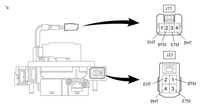
| *a | Component without harness connected (Spiral Cable Sub-assembly) | - | - |
Standard Resistance:
| Tester Connection | Condition | Specified Condition |
|---|---|---|
| z11-2 (BTM) - J23-1 (BTM) | Always | 3 Ω or less |
| z11-3 (ETM) - J23-3 (ETM) | Always | 3 Ω or less |
| z11-1 (EHT) - J23-2 (EHT) | Always | Below 0.1 Ω |
| z11-4 (BHT) - J23-4 (BHT) | Always | Below 0.1 Ω |
| NG | | REPLACE SPIRAL CABLE SUB-ASSEMBLY |
|
| 8. | CHECK HARNESS AND CONNECTOR (SPIRAL CABLE SUB-ASSEMBLY BODY GROUND) |
(a) Disconnect the J23 spiral cable sub-assembly connector.
(b) Measure the resistance according to the value(s) in the table below.
Standard Resistance:
| Tester Connection | Condition | Specified Condition |
|---|---|---|
| J23-2 (EHT) - Body ground | Always | Below 1 Ω |
| NG | | REPAIR OR REPLACE HARNESS OR CONNECTOR |
|
| 9. | INSPECT STEERING WHEEL HEATER UNIT (THERMISTOR/HEATER/THERMOSTAT) |
| (a) Disconnect the B steering vibration and heater ECU connector. |
|
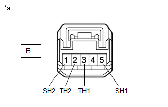
(b) Measure the resistance according to the value(s) in the table below.
Standard Resistance:
| Tester Connection | Condition | Specified Condition |
|---|---|---|
| B-3 (TH1) - B-2 (TH2) | 10 to 30°C (50 to 86°F) | 4.228 to 8.701 kΩ |
| B-5 (SH1) - B-1 (SH2) | 20°C (68°F) | 2.43 to 2.89 Ω |
| OK | | REPLACE STEERING VIBRATION AND HEATER ECU |
| NG | | REPLACE STEERING WHEEL ASSEMBLY |
 Problem Symptoms Table
PROBLEM SYMPTOMS TABLE HINT: Use the table below to help determine the cause of problem symptoms. If multiple suspected areas are listed, the potential causes of the symptoms are listed in order of pr ...
 System Description
SYSTEM DESCRIPTION HEATED STEERING WHEEL SYSTEM (a) The heated steering wheel system heats the steering wheel assembly when the steering heater switch (Integration control and panel assembly) is opera ...
Other materials:
Lexus RX (RX 350L, RX450h) 2016-2026 Repair Manual > Navigation System: Noise Occurs
PROCEDURE 1. CHECK NOISE CONDITION (a) Check from which direction the noise comes (front left or right, or rear left or right). OK: The location of the noise source can be determined. NG GO TO STEP 3
OK 2. CHECK SPEAKERS (a) Check the installation condi ...
Lexus RX (RX 350L, RX450h) 2016-2026 Repair Manual > Power Window Control System: Operation Check
OPERATION CHECK CHECK WINDOW LOCK FUNCTION HINT: Before performing the window lock switch operation check, make sure that the window lock switch is off (the switch is not pushed in). (a) Turn the window lock switch of the multiplex network master switch assembly on (pushed in) and check that the fr ...
Lexus RX (RX 350L, RX450h) 2016-{YEAR} Owners Manual
- For your information
- Pictorial index
- For safety and security
- Instrument cluster
- Operation of each component
- Driving
- Lexus Display Audio system
- Interior features
- Maintenance and care
- When trouble arises
- Vehicle specifications
- For owners
Lexus RX (RX 350L, RX450h) 2016-{YEAR} Repair Manual

0.0117