Lexus RX (RX 350L, RX450h) 2016-2026 Repair Manual: Removal
REMOVAL
CAUTION / NOTICE / HINT
The necessary procedures (adjustment, calibration, initialization, or registration) that must be performed after parts are removed and installed, or replaced during rear axle carrier sub-assembly removal/installation are shown below.
Necessary Procedures After Parts Removed/Installed/Replaced| Replaced Part or Performed Procedure | Necessary Procedure | Effect/Inoperative Function when Necessary Procedure not Performed | Link |
|---|---|---|---|
| Rear wheel alignment adjustment | Calibration |
| |
| Suspension, tires, etc. (The vehicle height changes because of suspension or tire replacement) |
|
| |
| Rear television camera assembly optical axis (Back camera position setting) | Parking Assist Monitor System | for Initialization: for Calibration: | |
| Panoramic View Monitor System | for Initialization: for Calibration: | |
| Initialize No. 1 headlight ECU sub-assembly LH | Lighting System (w/ Automatic Headlight Beam Level Control System) | |
HINT:
- Use the same procedure for the RH side and LH side.
- The following procedure is for the LH side.
PROCEDURE
1. REMOVE REAR WHEEL
Click here .gif)
2. REMOVE REAR SUSPENSION ARM COVER
Click here
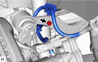
3. SEPARATE REAR FLEXIBLE HOSE
| (a) Remove the bolt and separate the rear flexible hose from the rear upper control arm assembly. |
|
4. SEPARATE REAR DISC BRAKE CALIPER ASSEMBLY
Click here
5. REMOVE REAR DISC
Click here
6. SEPARATE REAR SKID CONTROL SENSOR WIRE
Click here
7. REMOVE REAR AXLE HUB AND BEARING ASSEMBLY
Click here
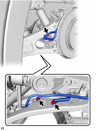
8. SEPARATE NO. 2 PARKING BRAKE WIRE ASSEMBLY
| (a) Remove the 3 bolts and separate the No. 2 parking brake wire assembly from the rear trailing arm assembly. |
|
9. REMOVE REAR TRAILING ARM ASSEMBLY
Click here
10. REMOVE REAR AXLE CARRIER SUB-ASSEMBLY
| (a) Using a jack and a wooden block, support the rear No. 2 suspension arm assembly. NOTICE:
|
|
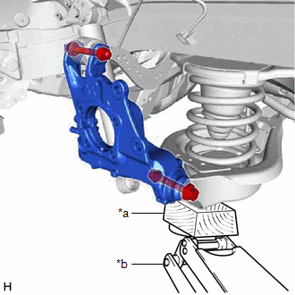
| (b) Remove the 2 bolts (A), and separate the rear lower shock absorber bracket sub-assembly from the rear axle carrier sub-assembly. |
|
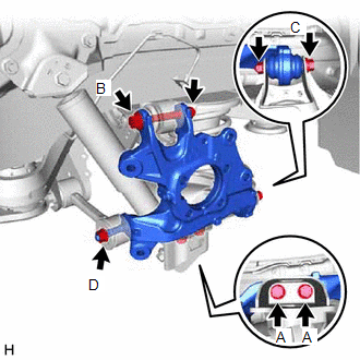
(c) Remove the bolt (B) and nut, and separate the rear upper control arm assembly from the rear axle carrier sub-assembly.
NOTICE:
Because the nut has its own stopper, do not turn the nut. Loosen the bolt with the nut secured.
(d) Remove the bolt (C) and nut, and separate the rear axle carrier sub-assembly from the rear No. 2 suspension arm assembly.
NOTICE:
Because the nut has its own stopper, do not turn the nut. Loosen the bolt with the nut secured.
(e) Remove the nut (D), spacer and rear axle carrier sub-assembly from the rear No. 1 suspension arm assembly.
11. REMOVE LOWER CONTROL ARM PIN (for TMMC Made)
| (a) Secure the rear axle carrier sub-assembly in a vise using aluminum plates. NOTICE: Do not overtighten the vise. |
|
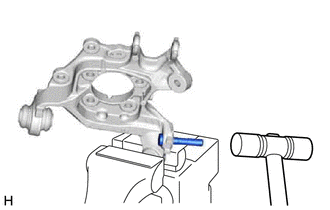
(b) Using a hammer, remove the lower control arm pin from the rear axle carrier sub-assembly.
 Components
COMPONENTS ILLUSTRATION *1 REAR AXLE HUB AND BEARING ASSEMBLY *2 REAR DISC *3 REAR DISC BRAKE CALIPER ASSEMBLY *4 REAR SKID CONTROL SENSOR WIRE *5 REAR SUSPENSION ARM COVER ...
 Installation
INSTALLATION CAUTION / NOTICE / HINT HINT:
Use the same procedure for the RH side and LH side.
The following procedure is for the LH side.
PROCEDURE 1. INSTALL LOWER CONTROL ARM PIN (for TMMC ...
Other materials:
Lexus RX (RX 350L, RX450h) 2016-2026 Repair Manual > Front Drive Shaft Assembly: Reassembly
REASSEMBLY PROCEDURE 1. INSTALL FRONT DRIVE SHAFT BEARING (for RH Side) (a) Using SST, a steel plate and a press, install a new front drive shaft bearing. SST: 09527-10011 NOTICE: The bearing should be completely installed. *a Steel Plate (b) Using a snap ring expander, ...
Lexus RX (RX 350L, RX450h) 2016-2026 Repair Manual > Panoramic Moon Roof System: Position Initialization Incomplete (B2343)
DESCRIPTION This DTC is stored when the sliding roof ECU (sliding roof drive gear assembly) or roof sunshade ECU (sliding roof drive gear assembly) has not been initialized. Sliding Roof DTC No. Detection Item DTC Detection Condition Trouble Area B2343 Position Initialization Incomple ...
Lexus RX (RX 350L, RX450h) 2016-{YEAR} Owners Manual
- For your information
- Pictorial index
- For safety and security
- Instrument cluster
- Operation of each component
- Driving
- Lexus Display Audio system
- Interior features
- Maintenance and care
- When trouble arises
- Vehicle specifications
- For owners
Lexus RX (RX 350L, RX450h) 2016-{YEAR} Repair Manual

0.0095