Lexus RX (RX 350L, RX450h) 2016-2026 Repair Manual: Installation
INSTALLATION
CAUTION / NOTICE / HINT
HINT:
- Use the same procedure for the RH side and LH side.
- The following procedure is for the LH side.
PROCEDURE
1. INSTALL LOWER CONTROL ARM PIN (for TMMC Made)
| (a) Secure the rear axle carrier sub-assembly in a vise using aluminum plates. NOTICE: Do not overtighten the vise. |
|
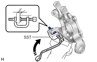
(b) Using SST, install a new lower control arm pin to the rear axle carrier sub-assembly as shown in the illustration.
SST: 09650-17011
2. TEMPORARILY INSTALL REAR AXLE CARRIER SUB-ASSEMBLY
| (a) Secure the rear axle carrier sub-assembly in a vise using aluminum plates. NOTICE: Do not overtighten the vise. |
|
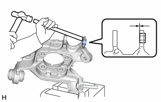
(b) Using a brass bar and a hammer, push out the bushing until it is positioned as shown in the illustration.
HINT:
Pushing out the bushing makes it easier to install the rear axle carrier sub-assembly.
| (c) Temporarily install the rear axle carrier sub-assembly to the rear No. 1 suspension arm assembly with the spacer and nut (A). NOTICE: Fully tighten the nut (A) after stabilizing the suspension. |
|
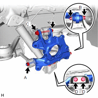
(d) Install the rear axle carrier sub-assembly to the rear No. 2 suspension arm assembly with the bolt (B) and nut.
Torque:
100 N·m {1020 kgf·cm, 74 ft·lbf}
NOTICE:
- Insert the bolt with the threaded end facing the front of the vehicle.
- Because the nut has its own stopper, do not turn the nut. Tighten the bolt with the nut secured.
(e) Install the rear axle carrier sub-assembly to the rear upper control arm assembly with the bolt (C) and nut.
Torque:
145 N·m {1479 kgf·cm, 107 ft·lbf}
NOTICE:
- Insert the bolt with the threaded end facing the rear of the vehicle.
- Because the nut has its own stopper, do not turn the nut. Tighten the bolt with the nut secured.
(f) Install the rear axle carrier sub-assembly to the rear lower shock absorber bracket sub-assembly with the 2 bolts (D).
Torque:
100 N·m {1020 kgf·cm, 74 ft·lbf}
(g) Slowly lower the rear No. 2 suspension arm assembly.
3. INSTALL REAR TRAILING ARM ASSEMBLY
Click here .gif)
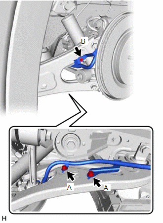
4. INSTALL NO. 2 PARKING BRAKE WIRE ASSEMBLY
| (a) Install the No. 2 parking brake wire assembly to the rear trailing arm assembly with the 3 bolts. Torque: Bolt (A) : 15 N·m {153 kgf·cm, 11 ft·lbf} Bolt (B) : 8.5 N·m {87 kgf·cm, 75 in·lbf} |
|
5. INSTALL REAR AXLE HUB AND BEARING ASSEMBLY
Click here
6. INSTALL REAR SKID CONTROL SENSOR WIRE
Click here
7. INSTALL REAR DISC
Click here
8. INSTALL REAR DISC BRAKE CALIPER ASSEMBLY
Click here
9. INSTALL REAR FLEXIBLE HOSE
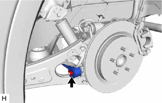
(a) Install the rear flexible hose to the rear upper control arm assembly with the bolt.
Torque:
18.8 N·m {192 kgf·cm, 14 ft·lbf}
10. STABILIZE SUSPENSION
Click here
11. INSTALL REAR NO. 1 SUSPENSION ARM ASSEMBLY
| (a) Install the rear No. 1 suspension arm assembly with the nut. Torque: 145 N·m {1479 kgf·cm, 107 ft·lbf} |
|
12. INSTALL REAR SUSPENSION ARM COVER
Click here
13. INSTALL REAR WHEEL
Click here
14. INSPECT AND ADJUST REAR WHEEL ALIGNMENT
Click here
15. CHECK FOR SPEED SENSOR SIGNAL
Click here
16. PERFORM INITIALIZATION
| |
| Parking Assist Monitor System | for Initialization: for Calibration: |
| Panoramic View Monitor System | for Initialization: for Calibration: |
| Lighting System (w/ Automatic Headlight Beam Level Control System) | |
 Removal
REMOVAL CAUTION / NOTICE / HINT The necessary procedures (adjustment, calibration, initialization, or registration) that must be performed after parts are removed and installed, or replaced during rea ...

Other materials:
Lexus RX (RX 350L, RX450h) 2016-2026 Repair Manual > Automatic Transaxle System: Monitor Drive Pattern
MONITOR DRIVE PATTERN MONITOR DRIVE PATTERN FOR ECT CAUTION: Perform the following procedure on a level surface while strictly observing all traffic laws and speed limits. HINT: Performing this drive pattern is one method to simulate ECM (ECT) malfunction detection conditions. Some DTCs may not be d ...
Lexus RX (RX 350L, RX450h) 2016-2026 Repair Manual > Sfi System: Crankshaft Position Sensor "A" Circuit Short to Ground (P033511,P033515,P03351F,P03352A,P033531)
DESCRIPTION The crankshaft position sensor system consists of a crankshaft position sensor plate and Magneto Resistance Element (MRE) type sensor. The crankshaft position sensor plate has 34 teeth at 10° intervals (2 teeth are missing for detecting top dead center), and is installed on the cranksha ...
Lexus RX (RX 350L, RX450h) 2016-{YEAR} Owners Manual
- For your information
- Pictorial index
- For safety and security
- Instrument cluster
- Operation of each component
- Driving
- Lexus Display Audio system
- Interior features
- Maintenance and care
- When trouble arises
- Vehicle specifications
- For owners
Lexus RX (RX 350L, RX450h) 2016-{YEAR} Repair Manual

0.0122