Lexus RX (RX 350L, RX450h) 2016-2026 Repair Manual: Inspection
INSPECTION
PROCEDURE
1. INSPECT STEERING PAD SWITCH ASSEMBLY
(a) Measure the resistance according to the value(s) in the table below.
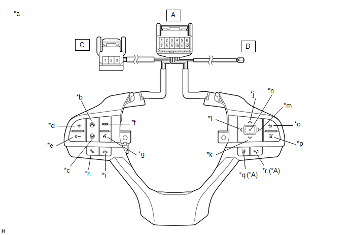 Text in Illustration
 | *A | w/ Lane Departure Alert System | - | - |
| *a | Component without harness connected (Steering Pad Switch Assembly) | *b | Seek+ |
| *c | Seek- | *d | Volume+ |
| *e | Volume- | *f | MODE |
| *g | Voice | *h | Off Hook |
| *i | On Hook | *j | Up |
| *k | Down | *l | Left |
| *m | Right | *n | Enter |
| *o | Back | *p | Top |
| *q | Lane Departure Alert | *r | Distance Control |
Standard Resistance:
| Tester Connection | Condition | Specified Condition |
|---|---|---|
| A-11 - A-8 | No switch pushed | 95 to 105 kΩ |
| Seek+ switch pushed | Below 2.5 Ω | |
| Seek- switch pushed | 313 to 345 Ω | |
| Volume+ switch pushed | 950 to 1050 Ω | |
| Volume- switch pushed | 2955 to 3265 Ω | |
| A-10 - A-8 | No switch pushed | 95 to 105 kΩ |
| MODE switch pushed | Below 2.5 Ω | |
| On hook switch pushed | 313 to 345 Ω | |
| Off hook switch pushed | 950 to 1050 Ω | |
| Voice switch pushed | 2955 to 3265 Ω | |
| A-3 - A-8 | No switch pushed | 95 to 105 kΩ |
| Left switch pushed | Below 2.5 Ω | |
| Up switch pushed | 313 to 345 Ω | |
| Down switch pushed | 950 to 1050 Ω | |
| Right switch pushed | 2955 to 3265 Ω | |
| A-2 - A-8 | No switch pushed | 95 to 105 kΩ |
| Enter switch pushed | Below 2.5 Ω | |
| Top switch pushed | 313 to 345 Ω | |
| Back switch pushed | 950 to 1050 Ω | |
| A-4 - A-7* | No switch pushed | 1 MΩ or higher |
| Distance control switch pushed | Below 2.5 Ω | |
| Lane departure alert switch pushed | 228 to 252 Ω | |
| A-6 - B-1 | Always | Below 2.5 Ω |
| A-7 - C-1 | Always | Below 2.5 Ω |
| A-12 - C-3 | Always | Below 2.5 Ω |
- *: w/ Lane Departure Alert System
HINT:
If the result is not as specified, replace the steering pad switch assembly.
(b) Check the illumination.
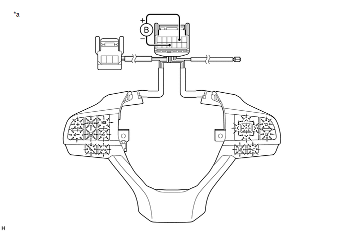
| *a | Component without harness connected (Steering Pad Switch Assembly) | - | - |
(1) Connect a positive (+) lead from the battery to terminal 5 and a negative (-) lead to terminal 9 of the steering pad switch assembly connector.
(2) Check that the steering pad switch assembly illumination illuminates.
OK:
The steering pad switch assembly illumination illuminates.
HINT:
If the result is not as specified, replace the steering pad switch assembly.
 Components
COMPONENTS ILLUSTRATION *1 STEERING PAD SWITCH ASSEMBLY - - N*m (kgf*cm, ft.*lbf): Specified torque - - ...
 Installation
INSTALLATION PROCEDURE 1. INSTALL STEERING PAD SWITCH ASSEMBLY (a) Engage the 2 claws and 2 pins to install the steering pad switch assembly. (b) Install the 2 screws. Torque: 2.4 N·m {24 kgf·cm, 2 ...
Other materials:
Lexus RX (RX 350L, RX450h) 2016-2026 Owners Manual > Basic operation of the
Remote Touch screen: Remote Touch
The Remote Touch can be used to operate the Remote Touch screens.
For details, refer to the "NAVIGATION SYSTEM OWNER'S MANUAL".
Vehicles with 8-inch display
Vehicles with 12.3-inch display
"HOME" button
Press this button to display the home screen.
*
button
Press this button t ...
Lexus RX (RX 350L, RX450h) 2016-2026 Repair Manual > Room Temperature Sensor (for Front): Installation
INSTALLATION PROCEDURE 1. INSTALL COOLER (ROOM TEMP. SENSOR) THERMISTOR (a) Connect the connector and aspirator. (b) Engage the 2 claws to install the cooler (room temp. sensor) thermistor as shown in the illustration. Install in this Direction 2. INSTALL LOWER INSTRUMENT FINISH PANEL SUB ...
Lexus RX (RX 350L, RX450h) 2016-{YEAR} Owners Manual
- For your information
- Pictorial index
- For safety and security
- Instrument cluster
- Operation of each component
- Driving
- Lexus Display Audio system
- Interior features
- Maintenance and care
- When trouble arises
- Vehicle specifications
- For owners
Lexus RX (RX 350L, RX450h) 2016-{YEAR} Repair Manual

0.0099