Lexus RX (RX 350L, RX450h) 2016-2026 Repair Manual: Drive Mode Select Switch Circuit
DESCRIPTION
The electronic throttle and the EPS character change by the operation of the drive mode select switch (combination switch assembly).
WIRING DIAGRAM
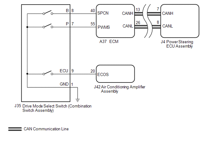
PROCEDURE
| 1. | CHECK THE PROBLEM SYMPTOMS |
(a) Check each symptom by checking the suspected areas in the table below.
| Result | Proceed to |
|---|---|
| SPORT, SPORT S/S+ mode or NORMAL mode is abnormal. | A |
| ECO mode is abnormal. | B |
| B | .gif) | GO TO AIR CONDITIONING SYSTEM |
|
.gif)
| 2. | CHECK CAN COMMUNICATION SYSTEM |
(a) Check for DTCs.
Click here .gif)
| Result | Proceed to |
|---|---|
| CAN communication system DTCs are not output. | A |
| CAN communication system DTCs are output. | B |
| B | | GO TO CAN COMMUNICATION SYSTEM |
|
| 3. | CHECK HARNESS AND CONNECTOR (DRIVE MODE SELECT SWITCH (COMBINATION SWITCH ASSEMBLY) - BODY GROUND) |
(a) Turn the engine switch off.
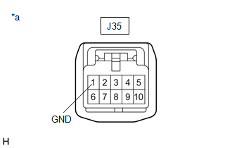
| (b) Disconnect the J35 drive mode select switch (combination switch assembly) connector. |
|
(c) Measure the resistance according to the value(s) in the table below.
Standard Resistance:
| Tester Connection | Condition | Specified Condition |
|---|---|---|
| J35-1 (GND) - Body ground | Always | Below 1 Ω |
| NG | | REPAIR OR REPLACE HARNESS OR CONNECTOR |
|
| 4. | INSPECT DRIVE MODE SELECT SWITCH (COMBINATION SWITCH ASSEMBLY) |
(a) Inspect drive mode select switch (combination switch assembly).
for U881E: Click here
for U881F: Click here
OK:
Drive mode select switch (combination switch assembly) is normal.
| NG | | REPLACE DRIVE MODE SELECT SWITCH (COMBINATION SWITCH ASSEMBLY) |
|
| 5. | CHECK HARNESS AND CONNECTOR (DRIVE MODE SELECT SWITCH (COMBINATION SWITCH ASSEMBLY) - ECM) |
(a) Reconnect the J35 drive mode select switch (combination switch assembly) connector.
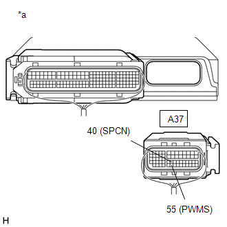
| (b) Disconnect the A37 ECM connectors. |
|
(c) Measure the resistance according to the value(s) in the table below.
Standard Resistance:
| Tester Connection | Condition | Specified Condition |
|---|---|---|
| A37-55 (PWMS) - Body ground | SPORT mode switch being turned and held | Below 50 Ω |
| A37-55 (PWMS) - Body ground | SPORT mode switch not turned | 10 kΩ or higher |
| A37-40 (SPCN) - Body ground | NORMAL mode switch being pushed and held | Below 50 Ω |
| A37-40 (SPCN) - Body ground | NORMAL mode switch not pushed | 10 kΩ or higher |
| OK | | REPLACE ECM |
| NG | | REPAIR OR REPLACE HARNESS OR CONNECTOR |
 Diagnostic Trouble Code Chart
DIAGNOSTIC TROUBLE CODE CHART Power Steering System DTC No. Detection Item DTC Detection Condition Warning Indicate Return-to-normal Condition Note Link C1511 Torque Sensor1 Tor ...
 Dtc Check / Clear
DTC CHECK / CLEAR CHECK DTCs (USING TECHSTREAM) (a) Turn the engine switch off. (b) Connect the Techstream to the DLC3. (c) Turn the engine switch on (IG). (d) Turn the Techstream on. (e) Enter the fo ...
Other materials:
Lexus RX (RX 350L, RX450h) 2016-2026 Repair Manual > Console Box Light (for Console Box Front Side): Installation
INSTALLATION PROCEDURE 1. INSTALL NO. 1 INTERIOR ILLUMINATION LIGHT ASSEMBLY (a) Connect the connector. (b) Engage the 2 claws to install the No. 1 interior illumination light assembly. 2. INSTALL REAR CONSOLE BOX GARNISH Click here 3. INSTALL CONSOLE PANEL SUB-ASSEMBLY Click here 4. INSTALL INS ...
Lexus RX (RX 350L, RX450h) 2016-2026 Repair Manual > Lighting System (w/ Automatic Headlight Beam Level Control System): Turn Signal Light Circuit
DESCRIPTION The combination meter assembly controls the illumination and turning off of the rear turn signal lights. WIRING DIAGRAM PROCEDURE 1. CHECK OPERATION (REAR TURN SIGNAL LIGHTS) (a) Check the operation of the rear turn signal lights. Result Proceed to LH side rear turn si ...
Lexus RX (RX 350L, RX450h) 2016-{YEAR} Owners Manual
- For your information
- Pictorial index
- For safety and security
- Instrument cluster
- Operation of each component
- Driving
- Lexus Display Audio system
- Interior features
- Maintenance and care
- When trouble arises
- Vehicle specifications
- For owners
Lexus RX (RX 350L, RX450h) 2016-{YEAR} Repair Manual

0.0132