Lexus RX (RX 350L, RX450h) 2016-2026 Repair Manual: Tilt and Telescopic Manual Switch Circuit
DESCRIPTION
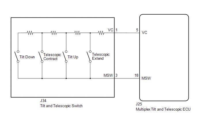
Different voltage values are sent to the multiplex tilt and telescopic ECU by operating the tilt and telescopic switch. The multiplex tilt and telescopic ECU then judges which motor and in which direction that motor should operate based on the voltage value.
WIRING DIAGRAM
PROCEDURE
| 1. | READ VALUE USING TECHSTREAM (TILT UP/DOWN SWITCH, TELESCOPIC SHORT/LONG SWITCH) |
| (a) Turn the engine switch off. |
|
(b) Connect the Techstream to the DLC3.
(c) Turn the engine switch on (IG).
(d) Turn the Techstream on.
(e) Check the tilt and telescopic switch.
(f) Enter the following menus: Body Electrical / Tilt & Telescopic / Data List.
Body Electrical > Tilt&Telescopic > Data List| Tester Display | Measurement Item | Range | Normal Condition | Diagnostic Note |
|---|---|---|---|---|
| Tilt Up Switch | Input state of tilt up switch | ON or OFF | ON: Tilt up switch activated OFF: Tilt up switch not activated | - |
| Tilt Down Switch | Input state of tilt down switch | ON or OFF | ON: Tilt down switch activated OFF: Tilt down switch not activated | - |
| Telesco Short Switch | Input state of telescopic contract switch | ON or OFF | ON: Telescopic contract switch activated OFF: Telescopic contract switch not activated | - |
| Telesco Long Switch | Input state of telescopic extend switch | ON or OFF | ON: Telescopic extend switch activated OFF: Telescopic extend switch not activated | - |
| Tester Display |
|---|
| Tilt Up Switch |
| Tilt Down Switch |
| Telesco Short Switch |
| Telesco Long Switch |
OK:
"ON" is displayed on the Techstream screen when each switch is turned on.
"OFF" is displayed on the Techstream screen when each switch is turned off.
| OK | .gif) | REPLACE MULTIPLEX TILT AND TELESCOPIC ECU |
|
.gif)
| 2. | CHECK HARNESS AND CONNECTOR (MULTIPLEX TILT AND TELESCOPIC ECU - TILT AND TELESCOPIC SWITCH) |
(a) Disconnect the J25 multiplex tilt and telescopic ECU connector.
(b) Disconnect the J34 tilt and telescopic switch connector.
(c) Measure the resistance according to the value(s) in the table below.
Standard Resistance:
| Tester Connection | Condition | Specified Condition |
|---|---|---|
| J25-5 (VC) - J34-1 (VC) | Always | Below 1 Ω |
| J25-18 (MSW) - J34-3 (MSW) | Always | Below 1 Ω |
| J25-5 (VC) or J34-1 (VC) - Body ground | Always | 10 kΩ or higher |
| J25-18 (MSW) or J34-3 (MSW) - Body ground | Always | 10 kΩ or higher |
| NG | | REPAIR OR REPLACE HARNESS OR CONNECTOR |
|
| 3. | CHECK MULTIPLEX TILT AND TELESCOPIC ECU (VC TERMINAL VOLTAGE) |
| (a) Reconnect the J25 multiplex tilt and telescopic ECU connector. |
|
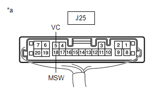
(b) Measure the voltage according to the value(s) in the table below.
Standard Voltage:
| Tester Connection | Condition | Specified Condition |
|---|---|---|
| J25-5 (VC) - J25-18 (MSW) | Engine switch on (IG) | 4.9 to 5.1 V |
| NG | | REPLACE MULTIPLEX TILT AND TELESCOPIC ECU |
|
| 4. | CHECK TILT AND TELESCOPIC SWITCH |
| (a) Remove the tilt and telescopic switch. Click here |
|
.gif)
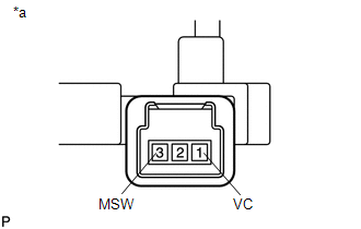
(b) Measure the resistance according to the value(s) in the table below.
Standard Resistance:
| Tester Connection | Condition | Specified Condition |
|---|---|---|
| 1 (VC) - 3 (MSW) | Tilt up | 342 to 378 Ω |
| Tilt down | 1890.5 to 2089.5 Ω | |
| Telescopic contract | 750.5 to 829.5 Ω | |
| Telescopic extend | 152 to 168 Ω |
| OK | | PROCEED TO NEXT SUSPECTED AREA SHOWN IN PROBLEM SYMPTOMS TABLE |
| NG | | REPLACE TILT AND TELESCOPIC SWITCH |
 Terminals Of Ecu
TERMINALS OF ECU MULTIPLEX TILT AND TELESCOPIC ECU *a Component without harness connected (Multiplex Tilt and Telescopic ECU) - - (a) Measure the voltage and resistance according to the v ...
 Lost Communication with Main Body ECU (U0142,U0208)
DESCRIPTION The multiplex tilt and telescopic ECU receives signals from the main body ECU (multiplex network body ECU) and position control ECU and switch assembly LH via CAN communication. DTC No. ...
Other materials:
Lexus RX (RX 350L, RX450h) 2016-2026 Repair Manual > Seat Heater Switch (for Rear Side): Inspection
INSPECTION PROCEDURE 1. INSPECT REFRESHING SEAT SWITCH (for Rear Side) (a) Apply battery voltage and check the operation of the switch according to the table below. OK: Battery Connection Condition Specified Condition Battery positive (+) → Terminal 7 Battery negative (-) → Termin ...
Lexus RX (RX 350L, RX450h) 2016-2026 Repair Manual > Smart Access System With Push-button Start (for Entry Function): Back Door Entry Lock Function does not Operate
DESCRIPTION If the entry lock function does not operate for the back door only, but the entry unlock function operates, the request code is being transmitted properly from the back door. In this case, there may be a problem related to the lock switch (connection between the back door opener switch a ...
Lexus RX (RX 350L, RX450h) 2016-{YEAR} Owners Manual
- For your information
- Pictorial index
- For safety and security
- Instrument cluster
- Operation of each component
- Driving
- Lexus Display Audio system
- Interior features
- Maintenance and care
- When trouble arises
- Vehicle specifications
- For owners
Lexus RX (RX 350L, RX450h) 2016-{YEAR} Repair Manual

0.0149