Lexus RX (RX 350L, RX450h) 2016-2026 Repair Manual: Installation
INSTALLATION
PROCEDURE
1. ALIGN FRONT WHEELS FACING STRAIGHT AHEAD
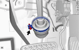
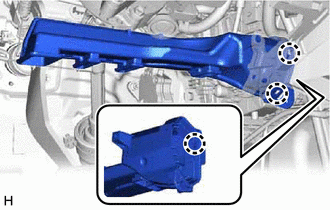
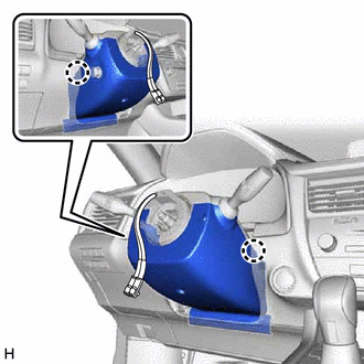
2. INSTALL STEERING COLUMN ASSEMBLY
NOTICE:
Make sure that the wire harness is not interfering with the steering column assembly.
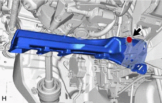
(a) Install the steering column assembly with the bolt and 2 nuts.
Torque:
36 N·m {367 kgf·cm, 27 ft·lbf}
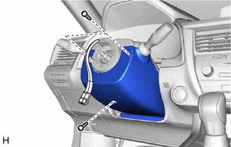
(b) Connect each connector and engage each wire harness clamp to the steering column assembly.
| (c) Connect the 2 connectors. |
|
(d) Engage the clamp.
3. INSTALL STEERING INTERMEDIATE SHAFT ASSEMBLY
| (a) Align the matchmarks on the steering intermediate shaft assembly and steering column assembly. |
|
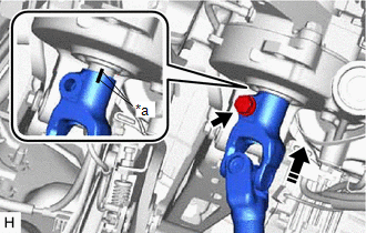
(b) Install the steering intermediate shaft assembly to the steering column assembly.
(c) Install a new bolt.
Torque:
64 N·m {653 kgf·cm, 47 ft·lbf}
| (d) Tighten the bolt. |
|
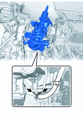
4. CONNECT STEERING INTERMEDIATE SHAFT ASSEMBLY
Click here .gif)
5. INSTALL STOP LIGHT SWITCH ASSEMBLY
Click here
6. INSTALL NO. 4 AIR DUCT SUB-ASSEMBLY
| (a) Engage the 3 claws to install a new No. 4 air duct sub-assembly. |
|
| (b) Install the bolt. Torque: 9.8 N·m {100 kgf·cm, 87 in·lbf} |
|
7. INSTALL FRONT NO. 1 CONSOLE BOX INSERT
Click here
8. INSTALL CONSOLE BOX ASSEMBLY
Click here
9. INSTALL CONSOLE REAR END PANEL SUB-ASSEMBLY
Click here
10. INSTALL CONSOLE PANEL SUB-ASSEMBLY
Click here
11. INSTALL SHIFT LEVER KNOB SUB-ASSEMBLY
Click here
12. INSTALL REAR CONSOLE UPPER PANEL
Click here
13. INSTALL LOWER NO. 1 INSTRUMENT PANEL AIRBAG ASSEMBLY
Click here
14. INSTALL TURN SIGNAL SWITCH ASSEMBLY WITH SPIRAL CABLE SUB-ASSEMBLY
NOTICE:
- Do not replace the spiral cable with sensor sub-assembly with the battery connected and the engine switch on (IG).
- Do not rotate the spiral cable with sensor sub-assembly without the steering wheel assembly installed, with the battery connected and the engine switch on (IG).
- Ensure that the steering wheel assembly is installed and aligned straight when inspecting the steering sensor.
.png) | Install in this direction |
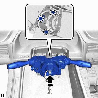
(a) Engage the 3 claws to install the turn signal switch assembly with spiral cable sub-assembly to the steering column assembly.
(b) Connect each connector to the turn signal switch assembly with spiral cable sub-assembly.
15. INSTALL UPPER STEERING COLUMN COVER
| (a) Engage the 6 clips to the upper steering column cover. |
|
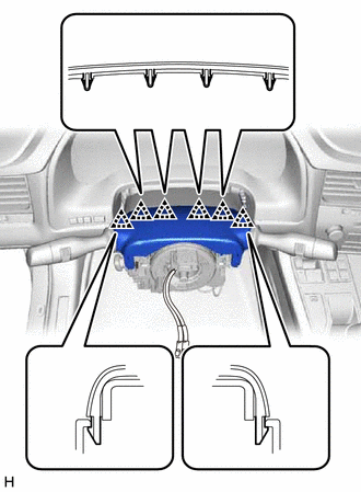
(b) Engage the 2 claws to install the upper steering column cover.
| | Install in this direction |
16. INSTALL LOWER STEERING COLUMN COVER
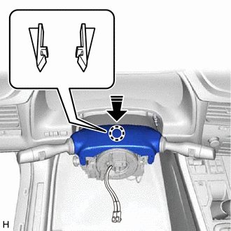
| (a) Engage the 2 claws to install the lower steering column cover. |
|
| (b) Install the 3 screws. Torque: 2.0 N·m {20 kgf·cm, 18 in·lbf} |
|
17. ALIGN FRONT WHEELS FACING STRAIGHT AHEAD
18. INSPECT AND ADJUST SPIRAL CABLE WITH SENSOR SUB-ASSEMBLY
Click here
19. INSTALL STEERING WHEEL ASSEMBLY
Click here
20. CHECK STEERING WHEEL CENTER POINT
21. INSTALL HORN BUTTON ASSEMBLY
Click here
22. CUSTOMIZE POWER TILT AND POWER TELESCOPIC STEERING COLUMN SYSTEM
(a) Set the auto tilt away function setting to the previous condition by changing the customize parameter.
Click here
23. PERFORM CALIBRATION OF TORQUE SENSOR ZERO POINT
Click here
24. ADJUST PARKING ASSIST MONITOR SYSTEM
Click here
25. ADJUST PANORAMIC VIEW MONITOR SYSTEM (w/ Panoramic View Monitor System)
Click here
26. ADJUST INTELLIGENT CLEARANCE SONAR SYSTEM (w/ Intelligent Clearance Sonar System)
Click here
 Inspection
INSPECTION PROCEDURE 1. INSPECT PRELOAD (a) Secure the steering column assembly in a vise using aluminum plates, cloths and wooden blocks. NOTICE:
Do not overtighten the vise, as the steering ...
 Reassembly
REASSEMBLY CAUTION / NOTICE / HINT NOTICE:
Do not drop the power steering ECU assembly, strike it with tools or subject it to impacts.
If the power steering ECU assembly is subjected to an impact ...
Other materials:
Lexus RX (RX 350L, RX450h) 2016-2026 Repair Manual > Headlight Dimmer Switch: Components
COMPONENTS ILLUSTRATION *A for Power Tilt and Power Telescopic Steering Column - - *1 HEADLIGHT DIMMER SWITCH ASSEMBLY *2 TILT AND TELESCOPIC SWITCH *3 WINDSHIELD WIPER SWITCH ASSEMBLY - - ...
Lexus RX (RX 350L, RX450h) 2016-2026 Repair Manual > Audio And Visual System (for 8 Inch Display): Air Conditioner ECU Vehicle Information Reading/Writing Processor Malfunction (B15F5)
DESCRIPTION This DTC is stored when items controlled by the air conditioning amplifier assembly cannot be customized via the audio and visual system vehicle customization screen. HINT: The air conditioning amplifier assembly controls the air conditioning system related items that are customizable vi ...
Lexus RX (RX 350L, RX450h) 2016-{YEAR} Owners Manual
- For your information
- Pictorial index
- For safety and security
- Instrument cluster
- Operation of each component
- Driving
- Lexus Display Audio system
- Interior features
- Maintenance and care
- When trouble arises
- Vehicle specifications
- For owners
Lexus RX (RX 350L, RX450h) 2016-{YEAR} Repair Manual

0.0093