Lexus RX (RX 350L, RX450h) 2016-2026 Repair Manual: Inspection
INSPECTION
PROCEDURE
1. INSPECT STEERING PAD SWITCH ASSEMBLY
(a) Measure the resistance according to the value(s) in the table below.
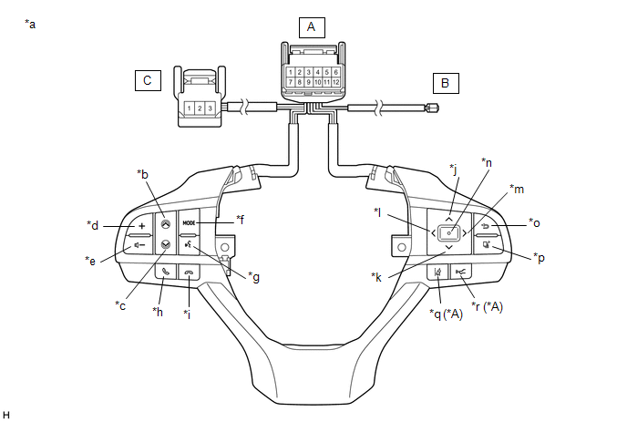 Text in Illustration
 | *A | w/ Lane Departure Alert System | - | - |
| *a | Component without harness connected (Steering Pad Switch Assembly) | *b | Seek+ |
| *c | Seek- | *d | Volume+ |
| *e | Volume- | *f | MODE |
| *g | Voice | *h | Off Hook |
| *i | On Hook | *j | Up |
| *k | Down | *l | Left |
| *m | Right | *n | Enter |
| *o | Back | *p | Top |
| *q | Lane Departure Alert | *r | Distance Control |
Standard Resistance:
| Tester Connection | Condition | Specified Condition |
|---|---|---|
| A-11 - A-8 | No switch pushed | 95 to 105 kΩ |
| Seek+ switch pushed | Below 2.5 Ω | |
| Seek- switch pushed | 313 to 345 Ω | |
| Volume+ switch pushed | 950 to 1050 Ω | |
| Volume- switch pushed | 2955 to 3265 Ω | |
| A-10 - A-8 | No switch pushed | 95 to 105 kΩ |
| MODE switch pushed | Below 2.5 Ω | |
| On hook switch pushed | 313 to 345 Ω | |
| Off hook switch pushed | 950 to 1050 Ω | |
| Voice switch pushed | 2955 to 3265 Ω | |
| A-3 - A-8 | No switch pushed | 95 to 105 kΩ |
| Left switch pushed | Below 2.5 Ω | |
| Up switch pushed | 313 to 345 Ω | |
| Down switch pushed | 950 to 1050 Ω | |
| Right switch pushed | 2955 to 3265 Ω | |
| A-2 - A-8 | No switch pushed | 95 to 105 kΩ |
| Enter switch pushed | Below 2.5 Ω | |
| Top switch pushed | 313 to 345 Ω | |
| Back switch pushed | 950 to 1050 Ω | |
| A-4 - A-7* | No switch pushed | 1 MΩ or higher |
| Distance control switch pushed | Below 2.5 Ω | |
| Lane departure alert switch pushed | 228 to 252 Ω | |
| A-6 - B-1 | Always | Below 2.5 Ω |
| A-7 - C-1 | Always | Below 2.5 Ω |
| A-12 - C-3 | Always | Below 2.5 Ω |
- *: w/ Lane Departure Alert System
HINT:
If the result is not as specified, replace the steering pad switch assembly.
(b) Check the illumination.
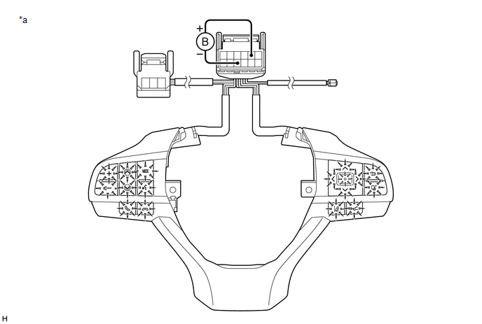
| *a | Component without harness connected (Steering Pad Switch Assembly) | - | - |
(1) Connect a positive (+) lead from the battery to terminal 5 and a negative (-) lead to terminal 9 of the steering pad switch assembly connector.
(2) Check that the steering pad switch assembly illumination illuminates.
OK:
The steering pad switch assembly illumination illuminates.
HINT:
If the result is not as specified, replace the steering pad switch assembly.
 Components
COMPONENTS ILLUSTRATION *1 STEERING PAD SWITCH ASSEMBLY - - N*m (kgf*cm, ft.*lbf): Specified torque - - ...
 Installation
INSTALLATION PROCEDURE 1. INSTALL STEERING PAD SWITCH ASSEMBLY (a) Engage the 2 claws and 2 pins to install the steering pad switch assembly. (b) Install the 2 screws. Torque: 2.4 N·m {24 kgf·cm, 2 ...
Other materials:
Lexus RX (RX 350L, RX450h) 2016-2026 Repair Manual > Power Back Door System (w/ Outside Door Control Switch): How To Proceed With Troubleshooting
CAUTION / NOTICE / HINT HINT:
The power back door system troubleshooting procedure is based on the premise that the smart access system (for Entry Function) is operating normally. Check the power back door system first before troubleshooting the power back door system.
Click here
Use the foll ...
Lexus RX (RX 350L, RX450h) 2016-2026 Repair Manual > Audio And Visual System (for 8 Inch Display): Black Screen
PROCEDURE 1. CHECK DISPLAY SETTING (a) Check that the display is not in screen off mode. OK: The display setting is not in screen off mode. NG CHANGE SCREEN TO SCREEN ON MODE
OK 2. CHECK IMAGE QUALITY SETTING (a) Check that the screen color quality can be ...
Lexus RX (RX 350L, RX450h) 2016-{YEAR} Owners Manual
- For your information
- Pictorial index
- For safety and security
- Instrument cluster
- Operation of each component
- Driving
- Lexus Display Audio system
- Interior features
- Maintenance and care
- When trouble arises
- Vehicle specifications
- For owners
Lexus RX (RX 350L, RX450h) 2016-{YEAR} Repair Manual

0.0103