Lexus RX (RX 350L, RX450h) 2016-2026 Repair Manual: Reassembly
REASSEMBLY
PROCEDURE
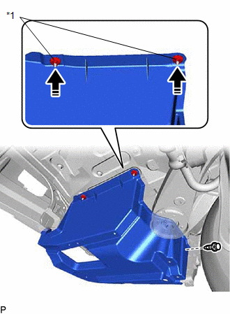
1. INSTALL REAR BUMPER UPPER RETAINER LH
(a) Engage the 2 guides as shown in the illustration to install the rear bumper upper retainer LH to the rear combination light assembly LH.
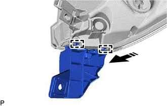
.png) | Install in this Direction |
(b) Engage the grommet.
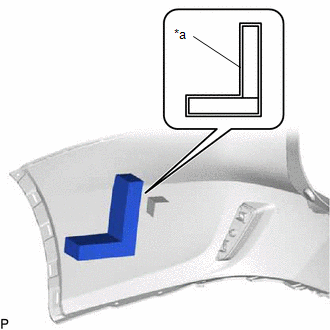
(c) Engage the guide and pin as shown in the illustration.
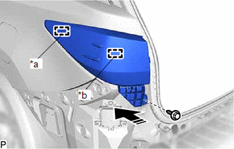
| *a | Guide |
| *b | Pin |
| | Install in this Direction |
(d) Install the rear bumper upper retainer LH with rear combination light assembly LH with the screw.
2. INSTALL REAR BUMPER UPPER RETAINER RH
HINT:
Use the same procedure as for the LH side.
3. INSTALL REAR COMBINATION LIGHT ASSEMBLY LH
Click here .gif)
4. INSTALL REAR COMBINATION LIGHT ASSEMBLY RH
HINT:
Use the same procedure as for the LH side.
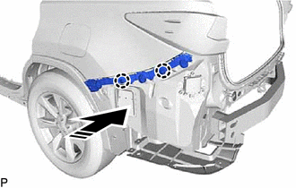
5. INSTALL NO. 1 REAR BUMPER REINFORCEMENT
| (a) Install the No. 1 rear bumper reinforcement with the 6 nuts. Torque: 35 N·m {357 kgf·cm, 26 ft·lbf} |
|
.png)
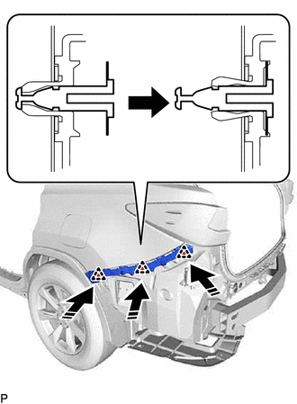
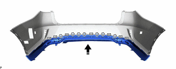
6. INSTALL REAR BUMPER ENERGY ABSORBER
(a) Engage the 2 guides as shown in the illustration to install the rear bumper energy absorber.
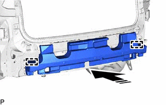
| | Install in this Direction |
7. INSTALL REAR BUMPER LOWER RETAINER LH
(a) Engage the claw as shown in the illustration.
| | Install in this Direction |
| (b) Install the lower rear bumper retainer LH with the 2 screws. |
|
.png)
8. INSTALL REAR BUMPER LOWER RETAINER RH
HINT:
Use the same procedure as for the LH side.
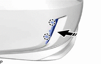
9. INSTALL NO. 2 LUGGAGE COMPARTMENT SIDE PROTECTOR COVER
(a) Engage the 2 No. 2 luggage compartment side protector cover clips.
| *1 | No. 2 Luggage Compartment Side Protector Cover Clip |
| | Install in this Direction |
(b) Install the No. 2 luggage compartment side protector cover with the clip.
10. INSTALL NO. 1 LUGGAGE COMPARTMENT SIDE PROTECTOR COVER
(a) Install the No. 1 luggage compartment side protector cover with the bolt and clip.
.png)
.png) | Bolt |
.png) | Clip |
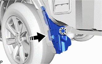
11. CONNECT REAR WHEEL HOUSE LINER LH
| (a) Connect the rear wheel house liner LH with the 2 screws and grommet. |
|
.png)
12. CONNECT REAR WHEEL HOUSE LINER RH
HINT:
Use the same procedure as for the LH side.
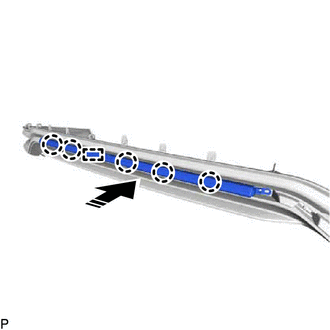
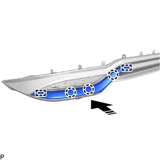
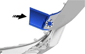
13. INSTALL REAR BUMPER SIDE RETAINER LH
(a) Engage the 2 claws as shown in the illustration.
| | Install in this Direction |
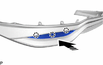
(b) Engage the 3 clips as shown in the illustration to install the rear bumper side retainer LH.
| | Install in this Direction |
14. INSTALL REAR BUMPER SIDE RETAINER RH
HINT:
Use the same procedure as for the LH side.
15. INSTALL REAR BUMPER MOULDING
(a) Engage the guide and 5 claws as shown in the illustration to install the rear bumper moulding.
| | Install in this Direction |
(b) w/o Kick Sensor:
| (1) Install the screw. |
|
.png)
16. INSTALL REAR BUMPER SIDE MOULDING LH
(a) Engage the 2 guides and 3 claws as shown in the illustration.
| | Install in this Direction |
| (b) Install the rear bumper side moulding LH with the 2 screws. |
|
.png)
17. INSTALL REAR BUMPER SIDE MOULDING RH
HINT:
Use the same procedure as for the LH side.
18. INSTALL REAR BUMPER PLATE RH
(a) Engage the claw as shown in the illustration.
| | Install in this Direction |
| (b) Install the rear bumper plate RH with the 2 clips. |
|
.png)
19. INSTALL REAR BUMPER SIDE SEAL LH
(a) Engage the 3 claws as shown in the illustration to install the rear bumper side seal LH to the rear bumper lower cover.
| | Install in this Direction |
20. INSTALL REAR BUMPER SIDE SEAL RH
HINT:
Use the same procedure as for the LH side.
21. INSTALL REAR BUMPER PAD
HINT:
When installing the rear bumper pad, heat the rear bumper assembly using a heat light.
Heating Temperature| Item | Temperature |
|---|---|
| Rear Bumper Assembly | 20 to 30°C (68 to 86°F) |
CAUTION:
- Do not touch the heat light and heated parts, touching the heat light may result in burns.
- Touching heated parts for a long time may result in burns.
.png)
| *a | Heated Part |
| *b | Heat Light |
NOTICE:
Do not heat the rear bumper assembly excessively.
(a) Clean the rear bumper assembly surface.
(1) Using a heat light, heat the rear bumper assembly surface.
(2) Remove the double-sided tape from the rear bumper assembly.
(3) Wipe off any tape adhesive residue with cleaner.
(b) Remove the release paper from a new rear bumper pad.
HINT:
After removing the release paper, keep the exposed adhesive free from foreign matter.
| (c) Install the rear bumper pad as shown in the illustration. HINT:
|
|
22. INSTALL REAR BUMPER PROTECTOR
HINT:
When installing the rear bumper protector, heat the rear bumper assembly using a heat light.
Heating Temperature| Item | Temperature |
|---|---|
| Rear Bumper Assembly | 20 to 30°C (68 to 86°F) |
CAUTION:
- Do not touch the heat light and heated parts, touching the heat light may result in burns.
- Touching heated parts for a long time may result in burns.
| *a | Heated Part |
| *b | Heat Light |
NOTICE:
Do not heat the rear bumper assembly excessively.
(a) Clean the rear bumper assembly surface.
(1) Using a heat light, heat the rear bumper assembly surface.
(2) Remove the double-sided tape from the rear bumper assembly.
(3) Wipe off any tape adhesive residue with cleaner.
(b) Remove the release paper from 2 new rear bumper protectors.
HINT:
After removing the release paper, keep the exposed adhesive free from foreign matter.
| (c) Install the 2 rear bumper protectors as shown in the illustration. HINT: Install the rear bumper protectors along the line on the rear bumper cover. |
|
23. INSTALL NO. 1 MOULDING TAPE
HINT:
- Use the same procedure for the LH side and RH side.
- When installing the No. 1 moulding tape, heat the rear bumper assembly using a heat light.
Heating Temperature:
| Item | Temperature |
|---|---|
| Rear Bumper Assembly | 20 to 30°C (68 to 86°F) |
CAUTION:
- Do not touch the heat light and heated parts, touching the heat light may result in burns.
- Touching heated parts for a long time may result in burns.
| *a | Heated Part |
| *b | Heat Light |
NOTICE:
Do not heat the rear bumper assembly excessively.
(a) Clean the rear bumper assembly surface.
(1) Using a heat light, heat the rear bumper assembly surface.
(2) Remove the double-sided tape from the rear bumper assembly.
(3) Wipe off any tape adhesive residue with cleaner.
(b) Remove the release paper from a new No. 1 moulding tape.
HINT:
After removing the release paper, keep the exposed adhesive free from foreign matter.
| (c) Install the No. 1 moulding tape as shown in the illustration. HINT: Press the No. 1 moulding tape firmly to install it. |
|
24. INSTALL REAR BUMPER LOWER COVER SUB-ASSEMBLY
(a) Engage the 7 guides and 7 claws as shown in the illustration.
| | Install in this Direction | - | - |
(b) Install the rear bumper lower cover sub-assembly with the 2 screws and 13 clips.
.png)
25. INSTALL REFLEX REFLECTOR ASSEMBLY LH
(a) Engage the 2 claws as shown in the illustration.
| | Install in this Direction |
| (b) Install the reflex reflector assembly LH with the screw. |
|
.png)
26. INSTALL REFLEX REFLECTOR ASSEMBLY RH
HINT:
Use the same procedure as for the LH side.
27. INSTALL ULTRASONIC SENSOR CLIP (w/o Intuitive Parking Assist System)
HINT:
When installing the ultrasonic sensor clip, heat the rear bumper assembly using a heat light.
Heating Temperature:
| Item | Temperature |
|---|---|
| Rear Bumper Assembly | 20 to 30°C (68 to 86°F) |
CAUTION:
- Do not touch the heat light and heated parts, touching the heat light may result in burns.
- Touching heated parts for a long time may result in burns.
| *a | Heated Part |
| *b | Heat Light |
NOTICE:
Do not heat the rear bumper assembly excessively.
(a) w/ Kick Sensor:
(1) Clean the rear bumper assembly surface.
- Using a heat light, heat the rear bumper assembly surface.
- Remove the double-sided tape from the rear bumper assembly.
- Wipe off any tape adhesive residue with cleaner.
(2) Using a brush or felt, apply primer or equivalent to the ultrasonic sensor clip installation area.
.png)
.png) | Primer |
(3) Remove the release paper from a new ultrasonic sensor clip.
HINT:
After removing the release paper, keep the exposed adhesive free from foreign matter.
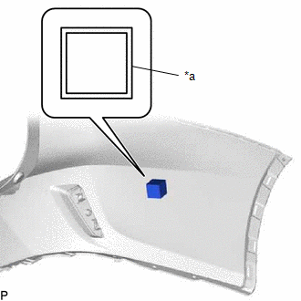
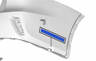
(4) Install the ultrasonic sensor clip as shown in the illustration.
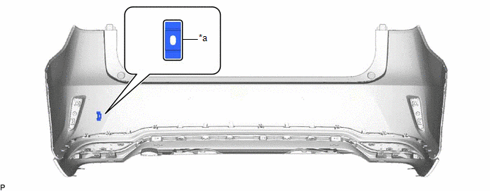
| *a | Line | - | - |
HINT:
Press the ultrasonic sensor clip firmly to install it.
28. INSTALL ULTRASONIC SENSOR CLIP (w/ Intuitive Parking Assist System)
HINT:
When installing the ultrasonic sensor clip, heat the rear bumper assembly using a heat light.
Heating Temperature:
| Item | Temperature |
|---|---|
| Rear Bumper Assembly | 20 to 30°C (68 to 86°F) |
CAUTION:
- Do not touch the heat light and heated parts, touching the heat light may result in burns.
- Touching heated parts for a long time may result in burns.
| *a | Heated Part |
| *b | Heat Light |
NOTICE:
Do not heat the rear bumper assembly excessively.
(a) Clean the rear bumper assembly surface.
(1) Using a heat light, heat the rear bumper assembly surface.
(2) Remove the double-sided tape from the rear bumper assembly.
(3) Wipe off any tape adhesive residue with cleaner.
(b) Using a brush or felt, apply primer or equivalent to the ultrasonic sensor clip installation area.
| | Primer |
(c) Remove the release paper from a new ultrasonic sensor clip.
HINT:
After removing the release paper, keep the exposed adhesive free from foreign matter.
(d) Install each ultrasonic sensor clip as shown in the illustration.
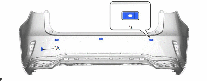
| *A | w/ Kick Sensor | - | - |
| *a | Line | - | - |
HINT:
Press the ultrasonic sensor clip firmly to install it.
29. INSTALL NO. 3 LUGGAGE ROOM WIRE (w/o Intuitive Parking Assist System)
(a) w/ Kick Sensor:
(1) Engage the clamp to install the No. 3 luggage room wire as shown in the illustration.
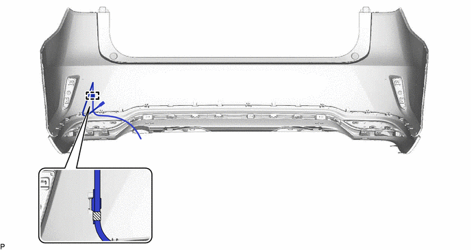
.png) | Tape | - | - |
30. INSTALL NO. 3 LUGGAGE ROOM WIRE (w/ Intuitive Parking Assist System)
(a) w/o Kick Sensor:
(1) Engage the 5 clamps to install the No. 3 luggage room wire.
.png)
(b) w/ Kick Sensor:
(1) Engage the 6 clamps to install the No. 3 luggage room wire as shown in the illustration.
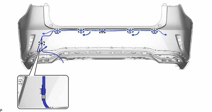
| | Tape | - | - |
31. INSTALL KICK DOOR CONTROL SENSOR WITH BRACKET (w/ Kick Sensor)
Click here
32. INSTALL REAR CORNER ULTRASONIC SENSOR RETAINER (w/ Intuitive Parking Assist System)
Click here
33. INSTALL REAR CENTER ULTRASONIC SENSOR RETAINER (w/ Intuitive Parking Assist System)
Click here
34. INSTALL REAR CORNER ULTRASONIC SENSOR (w/ Intuitive Parking Assist System)
Click here
35. INSTALL REAR CENTER ULTRASONIC SENSOR (w/ Intuitive Parking Assist System)
Click here
 Disassembly
DISASSEMBLY PROCEDURE 1. REMOVE REAR CENTER ULTRASONIC SENSOR (w/ Intuitive Parking Assist System) Click here 2. REMOVE REAR CORNER ULTRASONIC SENSOR (w/ Intuitive Parking Assist System) Click here ...

Other materials:
Lexus RX (RX 350L, RX450h) 2016-2026 Repair Manual > Window Defogger System: Parts Location
PARTS LOCATION ILLUSTRATION *1 SEMICONDUCTOR PWR INTEGRATION ECU *2 ENGINE ROOM RELAY BLOCK ASSEMBLY - ALT FUSE *3 REAR WINDOW DEFOGGER WIRE (BACK WINDOW GLASS) - - ILLUSTRATION *1 REAR WINDOW DEFOGGER SWITCH *2 DLC3 *3 RADIO RECEIVER ASSEMBLY *4 AIR CONDIT ...
Lexus RX (RX 350L, RX450h) 2016-2026 Repair Manual > Differential Oil Seal (for Lh Side): Components
COMPONENTS ILLUSTRATION *1 FRONT WHEEL OPENING EXTENSION PAD LH *2 NO. 3 ENGINE UNDER COVER *3 FRONT FENDER APRON SEAL LH - - ILLUSTRATION *1 FRONT DRIVE SHAFT OIL SEAL LH *2 O-RING *3 REFILL PLUG *4 OVERFLOW PLUG *5 DRAIN PLUG *6 GASKET Ti ...
Lexus RX (RX 350L, RX450h) 2016-{YEAR} Owners Manual
- For your information
- Pictorial index
- For safety and security
- Instrument cluster
- Operation of each component
- Driving
- Lexus Display Audio system
- Interior features
- Maintenance and care
- When trouble arises
- Vehicle specifications
- For owners
Lexus RX (RX 350L, RX450h) 2016-{YEAR} Repair Manual

0.0125