Lexus RX (RX 350L, RX450h) 2016-2026 Repair Manual: Disassembly
DISASSEMBLY
PROCEDURE
1. REMOVE REAR CENTER ULTRASONIC SENSOR (w/ Intuitive Parking Assist System)
Click here .gif)
2. REMOVE REAR CORNER ULTRASONIC SENSOR (w/ Intuitive Parking Assist System)
Click here
3. REMOVE REAR CENTER ULTRASONIC SENSOR RETAINER (w/ Intuitive Parking Assist System)
Click here
4. REMOVE REAR CORNER ULTRASONIC SENSOR RETAINER (w/ Intuitive Parking Assist System)
Click here
5. REMOVE KICK DOOR CONTROL SENSOR WITH BRACKET (w/ Kick Sensor)
Click here
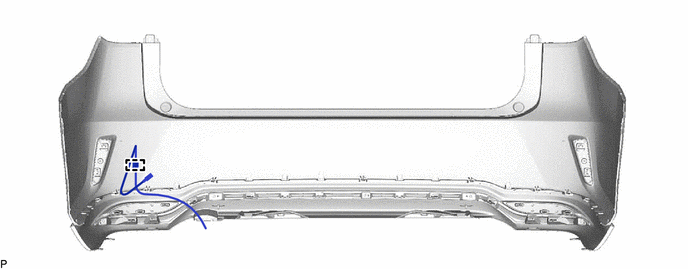
6. REMOVE NO. 3 LUGGAGE ROOM WIRE (w/o Intuitive Parking Assist System)
(a) w/ Kick Sensor:
(1) Disengage the clamp to remove the No. 3 luggage room wire.
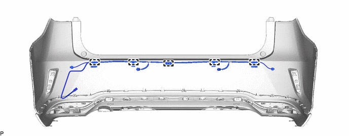
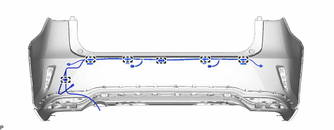
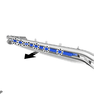
7. REMOVE NO. 3 LUGGAGE ROOM WIRE (w/ Intuitive Parking Assist System)
(a) w/o Kick Sensor:
(1) Disengage the 5 clamps to remove the No. 3 luggage room wire.
(b) w/ Kick Sensor:
(1) Disengage the 6 clamps to remove the No. 3 luggage room wire.
8. REMOVE ULTRASONIC SENSOR CLIP (w/o Intuitive Parking Assist System)
HINT:
When removing the ultrasonic sensor clip, heat the rear bumper assembly and ultrasonic sensor clip using a heat light.
Heating Temperature| Item | Temperature |
|---|---|
| Ultrasonic Sensor Clip and Rear Bumper Assembly | 20 to 30°C (68 to 86°F) |
CAUTION:
- Do not touch the heat light and heated parts, touching the heat light may result in burns.
- Touching heated parts for a long time may result in burns.
.png)
| *a | Heated Part |
| *b | Heat Light |
NOTICE:
Do not heat the rear bumper assembly or ultrasonic sensor clip excessively.
(a) w/ Kick Sensor:
(1) Using a heat light, heat the rear bumper assembly and ultrasonic sensor clip.
(2) Remove the ultrasonic sensor clip.
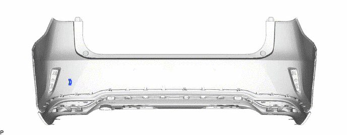
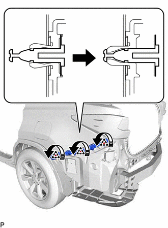
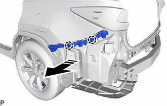
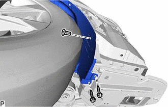
9. REMOVE ULTRASONIC SENSOR CLIP (w/ Intuitive Parking Assist System)
HINT:
When removing the ultrasonic sensor clip, heat the rear bumper assembly and ultrasonic sensor clip using a heat light.
Heating Temperature| Item | Temperature |
|---|---|
| Ultrasonic Sensor Clip and Rear Bumper Assembly | 20 to 30°C (68 to 86°F) |
CAUTION:
- Do not touch the heat light and heated parts, touching the heat light may result in burns.
- Touching heated parts for a long time may result in burns.
| *a | Heated Part |
| *b | Heat Light |
NOTICE:
Do not heat the rear bumper assembly or ultrasonic sensor clip excessively.
(a) Using a heat light, heat the rear bumper assembly and ultrasonic sensor clip.
(b) Remove each ultrasonic sensor clip.
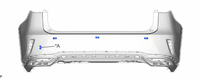
| *A | w/ Kick Sensor | - | - |
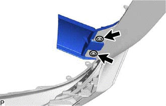
10. REMOVE REFLEX REFLECTOR ASSEMBLY LH
| (a) Remove the screw. |
|
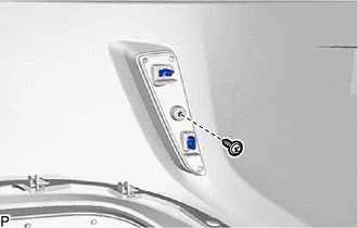
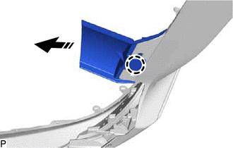
(b) Disengage the 2 claws as shown in the illustration to remove the reflex reflector assembly LH.
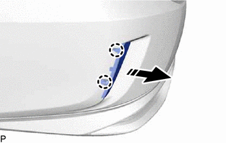
.png) | Remove in this Direction |
11. REMOVE REFLEX REFLECTOR ASSEMBLY RH
HINT:
Use the same procedure as for the LH side.
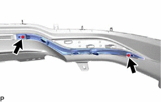
12. REMOVE REAR BUMPER LOWER COVER SUB-ASSEMBLY
(a) Remove the 2 screws and 13 clips.
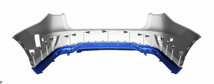
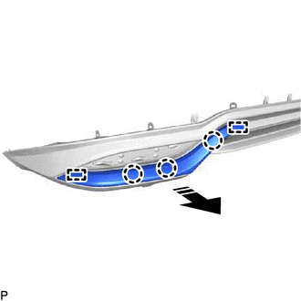
(b) Disengage the 7 claws and 7 guides as shown in the illustration to remove the rear bumper lower cover sub-assembly.
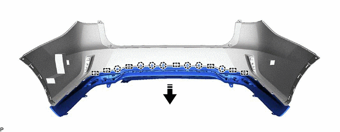
| | Remove in this Direction | - | - |
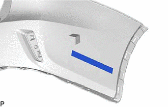
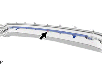
13. REMOVE NO. 1 MOULDING TAPE
| (a) Remove the No. 1 moulding tape. HINT: Use the same procedure for the RH side and LH side. |
|
14. REMOVE REAR BUMPER PROTECTOR
| (a) Remove the 2 rear bumper protectors. |
|

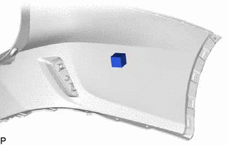
15. REMOVE REAR BUMPER PAD
| (a) Remove the rear bumper pad. HINT: Use the same procedure for the RH side and LH side. |
|
16. REMOVE REAR BUMPER SIDE SEAL LH
(a) Disengage the 3 claws as shown in the illustration to remove the rear bumper side seal LH from the rear bumper lower cover.
| | Remove in this Direction |
17. REMOVE REAR BUMPER SIDE SEAL RH
HINT:
Use the same procedure as for the LH side.
18. REMOVE REAR BUMPER PLATE RH
| (a) Remove the 2 clips. |
|
(b) Disengage the claw as shown in the illustration to remove the rear bumper plate RH.
| | Remove in this Direction |
19. REMOVE REAR BUMPER SIDE MOULDING LH
| (a) Remove the 2 screws. |
|
(b) Disengage the 3 claws and 2 guides as shown in the illustration to remove the rear bumper side moulding LH.
| | Remove in this Direction |
20. REMOVE REAR BUMPER SIDE MOULDING RH
HINT:
Use the same procedure as for the LH side.
21. REMOVE REAR BUMPER MOULDING
(a) w/o Kick Sensor:
| (1) Remove the screw. |
|
(b) Disengage the 5 claws and guide as shown in the illustration to remove the rear bumper moulding.
| | Remove in this Direction |
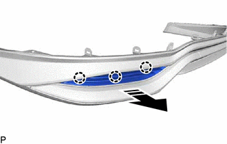
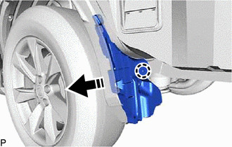
22. REMOVE REAR BUMPER SIDE RETAINER LH
(a) Disengage the 3 clips as shown in the illustration.
| | Remove in this Direction |
(b) Disengage the 2 claws as shown in the illustration to remove the rear bumper side retainer LH.
| | Remove in this Direction |
23. REMOVE REAR BUMPER SIDE RETAINER RH
HINT:
Use the same procedure as for the LH side.
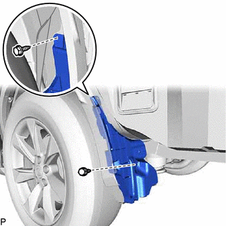
24. DISCONNECT REAR WHEEL HOUSE LINER LH
| (a) Remove the 2 screws and grommet and disconnect the rear wheel house liner LH. |
|
25. DISCONNECT REAR WHEEL HOUSE LINER RH
HINT:
Use the same procedure as for the LH side.
26. REMOVE NO. 2 LUGGAGE COMPARTMENT SIDE PROTECTOR COVER
(a) Remove the clip.
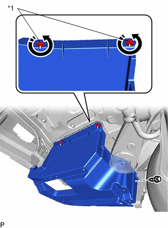
| *1 | No. 2 Luggage Compartment Side Protector Cover Clip |
| | Remove in this Direction |
(b) Disengage the 2 No. 2 luggage compartment side protector cover clips as shown in the illustration to remove the No. 2 luggage compartment side protector cover.
27. REMOVE NO. 1 LUGGAGE COMPARTMENT SIDE PROTECTOR COVER
(a) Remove the bolt, clip and No. 1 luggage compartment side protector cover.
.png) | Bolt |
.png) | Clip |
28. REMOVE REAR BUMPER LOWER RETAINER LH
| (a) Remove the 2 screws. |
|
(b) Disengage the claw as shown in the illustration to remove the rear bumper lower retainer LH.
| | Remove in this Direction |
29. REMOVE REAR BUMPER LOWER RETAINER RH
HINT:
Use the same procedure as for the LH side.
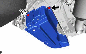
30. REMOVE REAR BUMPER ENERGY ABSORBER
(a) Disengage the 2 guides as shown in the illustration to remove the rear bumper energy absorber.
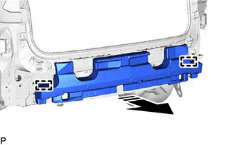
| | Remove in this Direction |
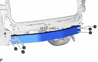
31. REMOVE NO. 1 REAR BUMPER REINFORCEMENT
| (a) Remove the 6 nuts and No. 1 rear bumper reinforcement. |
|
32. REMOVE REAR COMBINATION LIGHT ASSEMBLY LH
Click here
33. REMOVE REAR COMBINATION LIGHT ASSEMBLY RH
HINT:
Use the same procedure as for the LH side.
34. REMOVE REAR BUMPER UPPER RETAINER LH
| (a) Remove the screw and rear bumper upper retainer LH. |
|
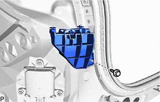
35. REMOVE REAR BUMPER UPPER RETAINER RH
HINT:
Use the same procedure as for the LH side.
 Installation
INSTALLATION PROCEDURE 1. INSTALL REAR BUMPER ASSEMBLY (a) w/ Intuitive Parking Assist System or Kick Sensor: (1) Connect the connector. (b) Engage the 2 claws as shown in the illustration. Ins ...
 Reassembly
REASSEMBLY PROCEDURE 1. INSTALL REAR BUMPER UPPER RETAINER LH (a) Engage the 2 guides as shown in the illustration to install the rear bumper upper retainer LH to the rear combination light assembly L ...
Other materials:
Lexus RX (RX 350L, RX450h) 2016-2026 Repair Manual > Oil Pan And Oil Level Sensor: Inspection
INSPECTION PROCEDURE 1. INSPECT ENGINE OIL LEVEL SENSOR (a) Measure the resistance according to the value(s) in the table below. Standard Resistance: Tester Connection Condition Specified Condition 1 - Body ground ON Below 1 Ω OFF 10 kΩ or higher If the result is not as ...
Lexus RX (RX 350L, RX450h) 2016-2026 Repair Manual > Immobiliser System: How To Proceed With Troubleshooting
CAUTION / NOTICE / HINT HINT:
Use this procedure to troubleshoot the immobiliser system.
*: Use the Techstream.
PROCEDURE 1. VEHICLE BROUGHT TO WORKSHOP
NEXT 2. CUSTOMER PROBLEM ANALYSIS HINT:
In troubleshooting, confirm that the problem symptoms have be ...
Lexus RX (RX 350L, RX450h) 2016-{YEAR} Owners Manual
- For your information
- Pictorial index
- For safety and security
- Instrument cluster
- Operation of each component
- Driving
- Lexus Display Audio system
- Interior features
- Maintenance and care
- When trouble arises
- Vehicle specifications
- For owners
Lexus RX (RX 350L, RX450h) 2016-{YEAR} Repair Manual

0.0129