Lexus RX (RX 350L, RX450h) 2016-2026 Repair Manual: Wheel Opening Moulding(for Rear Side)
Components
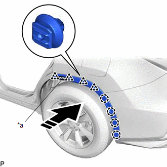
COMPONENTS
ILLUSTRATION
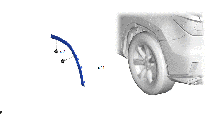
| *1 | QUARTER OUTSIDE MOULDING SUB-ASSEMBLY | - | - |
| ● | Non-reusable part | - | - |
Removal
REMOVAL
CAUTION / NOTICE / HINT
HINT:
- Use the same procedure for the RH side and LH side.
- The following procedure is for the LH side.
PROCEDURE
1. REMOVE QUARTER OUTSIDE MOULDING SUB-ASSEMBLY
HINT:
When removing the quarter outside moulding sub-assembly, heat the vehicle body and quarter outside moulding sub-assembly using a heat light.
Heating Temperature| Item | Temperature |
|---|---|
| Vehicle Body | 40 to 60°C (104 to 140°F) |
| Quarter Outside Moulding Sub-assembly | 20 to 30°C (68 to 86°F) |
CAUTION:
- Do not touch the heat light and heated parts, touching the heat light may result in burns.
- Touching heated parts for a long time may result in burns.
.png)
| *a | Heated Part |
| *b | Heat Light |
NOTICE:
Do not heat the vehicle body or quarter outside moulding sub-assembly excessively.
| (a) Using a 4 mm hexagon socket wrench, remove the screw. |
|
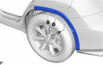
(b) Remove the 2 clips.
(c) Pull back the edge of the rear wheel house liner and disengage the 4 claws by pushing the area indicated by the arrow in the illustration with a finger.
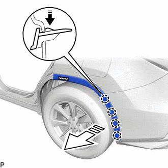
.png) | Remove in this Direction (1) |
.png) | Remove in this Direction (2) |
NOTICE:
- Do not apply excessive force when pulling back the rear wheel house liner.
- To avoid damaging the claws, do not forcibly pull the quarter outside moulding sub-assembly.
(d) Using a heat light, heat the quarter outside moulding sub-assembly.
(e) Disengage the 4 clips and separate the double-sided tape to remove the quarter outside moulding sub-assembly.
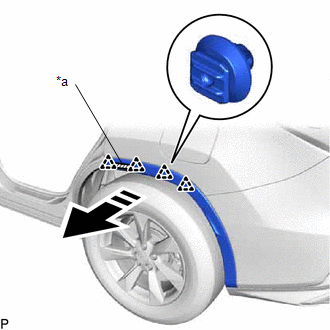
| *a | Double-sided Tape |
| | Remove in this Direction |
Installation
INSTALLATION
CAUTION / NOTICE / HINT
HINT:
- Use the same procedure for the RH side and LH side.
- The following procedure is for the LH side.
PROCEDURE
1. INSTALL QUARTER OUTSIDE MOULDING SUB-ASSEMBLY
HINT:
When installing a new quarter outside moulding sub-assembly, heat the vehicle body and quarter outside moulding sub-assembly using a heat light.
CAUTION:
- Do not touch the heat light and heated parts, touching the heat light may result in burns.
- Touching heated parts for a long time may result in burns.
.png)
| *a | Heated Part |
| *b | Heat Light |
| Item | Temperature |
|---|---|
| Vehicle Body | 40 to 60°C (104 to 140°F) |
| Quarter Outside Moulding Sub-assembly | 20 to 30°C (68 to 86°F) |
NOTICE:
Do not heat the vehicle body or quarter outside moulding sub-assembly excessively.
(a) Clean the vehicle body surface.
(1) Using a heat light, heat the vehicle body surface.
(2) Remove any double-sided tape from the vehicle body.
(3) Wipe off any tape adhesive residue with cleaner.
(b) Remove the release paper from a new quarter outside moulding sub-assembly.
HINT:
After removing the release paper, keep the exposed adhesive free from foreign matter.
(c) Engage the 4 clips and attach the double-sided tape.
| *a | Double-sided Tape |
.png) | Install in this Direction |
HINT:
Press the quarter outside moulding sub-assembly to install it.
(d) Engage the 4 claws.
(e) Using a 4 mm hexagon socket wrench, install the screw.
(f) Install the quarter outside moulding sub-assembly with the 2 clips.
 Wheel Opening Moulding(for Front Side)
ComponentsCOMPONENTS ILLUSTRATION *1 FRONT FENDER MOULDING SUB-ASSEMBLY *2 FRONT FENDER SPLASH SHIELD SUB-ASSEMBLY InstallationINSTALLATION CAUTION / NOTICE / HINT HINT:
Use the same p ...

Other materials:
Lexus RX (RX 350L, RX450h) 2016-2026 Repair Manual > Sfi System: Starter Relay Circuit Short to Battery (P061512)
MONITOR DESCRIPTION While the engine is being cranked, positive battery voltage is applied to terminal STA of the ECM. If the ECM detects the starter control (STA) signal while the vehicle is being driven, it determines that there is a malfunction in the STA circuit. The ECM then illuminates the MIL ...
Lexus RX (RX 350L, RX450h) 2016-2026 Repair Manual > Front Camera System: Dtc Check / Clear
DTC CHECK / CLEAR CHECK FOR DTC (a) Connect the Techstream to the DLC3. (b) Turn the engine switch on (IG). (c) Turn the Techstream on. (d) Enter the following menus: Chassis / Front Recognition Camera / Trouble Codes. Chassis > Front Recognition Camera > Trouble Codes (e) Check for DTCs (Test ...
Lexus RX (RX 350L, RX450h) 2016-{YEAR} Owners Manual
- For your information
- Pictorial index
- For safety and security
- Instrument cluster
- Operation of each component
- Driving
- Lexus Display Audio system
- Interior features
- Maintenance and care
- When trouble arises
- Vehicle specifications
- For owners
Lexus RX (RX 350L, RX450h) 2016-{YEAR} Repair Manual

0.0089