Lexus RX (RX 350L, RX450h) 2016-2026 Repair Manual: Lost Communication With Headlamp Control Module "B" (U0242)
DESCRIPTION
- The No. 1 headlight ECU sub-assembly LH communicates with the No. 1 headlight ECU sub-assembly RH via CAN communication. If communication between the No. 1 headlight ECU sub-assembly LH and No. 1 headlight ECU sub-assembly RH stops, the No. 1 headlight ECU sub-assembly LH will store this DTC.
- The No. 1 headlight ECU sub-assembly LH communicates with the No. 1 headlight ECU sub-assembly RH via LIN communication. If communication between the No. 1 headlight ECU sub-assembly LH and No. 1 headlight ECU sub-assembly RH stops, the No. 1 headlight ECU sub-assembly LH will store this DTC.
| DTC No. | Detection Item | DTC Detection Condition | Trouble Area | DTC Output from |
|---|---|---|---|---|
| U0242 | Lost Communication With Headlamp Control Module "B" |
|
| AFS |
| DTC No. | Detection Item | DTC Detection Condition | Trouble Area | DTC Output from |
|---|---|---|---|---|
| U0242 | Lost Communication With Headlamp Control Module "B" |
|
| HL AutoLeveling |
| Pattern | DTC output part name (Display on Techstream) | Suspected Area (Malfunction Status) |
|---|---|---|
| Headlight ECU Sub-assembly LH (AFS) | ||
| U0242 | ||
| ○: DTC is output | ||
| Pattern 1 | ○ |
|
| Pattern | DTC output part name (Display on Techstream) | Suspected Area (Malfunction Status) |
|---|---|---|
| Headlight ECU Sub-assembly LH (HL AutoLeveling) | ||
| U0242 | ||
| ○: DTC is output | ||
| Pattern 1 | ○ |
|
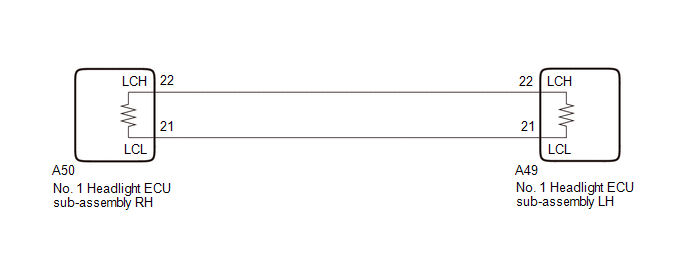
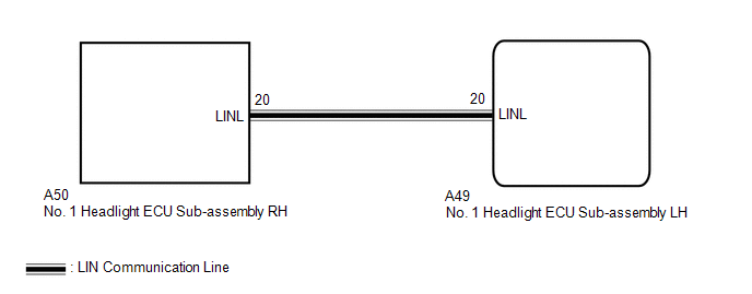
WIRING DIAGRAM
for Multiple Beam Headlight
for Single Beam Headlight
CAUTION / NOTICE / HINT
NOTICE:
-
If the No. 1 headlight ECU sub-assembly LH has been replaced, it is necessary to synchronize the vehicle information and initialize the No. 1 headlight ECU sub-assembly LH.
Click here
.gif)
-
If the headlight assembly LH has been replaced, it is necessary to synchronize the vehicle information and initialize the No. 1 headlight ECU sub-assembly LH.*
Click here
- When replacing the No. 1 headlight ECU sub-assembly LH, always replace it with a new one. If a No. 1 headlight ECU sub-assembly LH which was installed to another vehicle is used, the information stored in it will not match the information from the vehicle and a DTC may be stored.
-
When replacing the headlight assembly LH, always replace it with a new one. If a headlight assembly LH which was installed to another vehicle is used, the information stored in it will not match the information from the vehicle and a DTC may be stored.*
- *: for TMMC Made
PROCEDURE
| 1. | CONFIRM MODEL |
(a) Choose the model to be inspected.
| Result | Proceed to |
|---|---|
| for Multiple Beam Headlight | A |
| for Single Beam Headlight | B |
| B | .gif) | GO TO STEP 7 |
|
.gif)
| 2. | CHECK FOR DTC |
(a) Connect the Techstream to the DLC3.
(b) Turn the engine switch on (IG).
(c) Turn the Techstream on.
(d) Enter the following menus: Body Electrical / AFS / Trouble Codes.
(e) Check for DTCs.
Body Electrical > AFS > Trouble CodesOK:
DTC U0242 is not output.
| OK | | USE SIMULATION METHOD TO CHECK |
|
| 3. | CHECK HARNESS AND CONNECTOR (NO. 1 HEADLIGHT ECU SUB-ASSEMBLY LH - NO. 1 HEADLIGHT ECU SUB-ASSEMBLY RH) |
(a) Disconnect the A49 No. 1 headlight ECU sub-assembly LH connector.
(b) Disconnect the A50 No. 1 headlight ECU sub-assembly RH connector.
(c) Measure the resistance according to the value(s) in the table below.
Standard Resistance:
| Tester Connection | Condition | Specified Condition |
|---|---|---|
| A49-22 (LCH) - A50-22 (LCH) | Always | Below 1 Ω |
| A49-21 (LCL) - A50-21 (LCL) | Always | Below 1 Ω |
| A49-22 (LCH) or A50-22 (LCH) - Body ground | Always | 10 kΩ or higher |
| A49-21 (LCL) or A50-21 (LCL) - Body ground | Always | 10 kΩ or higher |
| NG | | REPAIR OR REPLACE HARNESS OR CONNECTOR |
|
| 4. | REPLACE NO. 1 HEADLIGHT ECU SUB-ASSEMBLY RH |
(a) Replace the No. 1 headlight ECU sub-assembly RH with a new one.
Click here
|
| 5. | CLEAR DTC |
(a) Connect the Techstream to the DLC3.
(b) Turn the engine switch on (IG).
(c) Turn the Techstream on.
(d) Enter the following menus: Body Electrical / AFS / Trouble Codes.
(e) Clear the DTCs.
Body Electrical > AFS > Clear DTCs
|
| 6. | CHECK FOR DTC |
(a) Connect the Techstream to the DLC3.
(b) Turn the engine switch on (IG).
(c) Turn the Techstream on.
(d) Enter the following menus: Body Electrical / AFS / Trouble Codes.
(e) Check for DTCs.
Body Electrical > AFS > Trouble CodesOK:
DTC U0242 is not output.
| OK | | END (NO. 1 HEADLIGHT ECU SUB-ASSEMBLY RH WAS DEFECTIVE) |
| NG | | REPLACE NO. 1 HEADLIGHT ECU SUB-ASSEMBLY LH |
| 7. | CHECK FOR DTC |
(a) Connect the Techstream to the DLC3.
(b) Turn the engine switch on (IG).
(c) Turn the Techstream on.
(d) Enter the following menus: Body Electrical / HL AutoLeveling / Trouble Codes.
(e) Check for DTCs.
Body Electrical > HL AutoLeveling > Trouble CodesOK:
DTC U0242 is not output.
| OK | | USE SIMULATION METHOD TO CHECK |
|
| 8. | CHECK HARNESS AND CONNECTOR (NO. 1 HEADLIGHT ECU SUB-ASSEMBLY LH - NO. 1 HEADLIGHT ECU SUB-ASSEMBLY RH) |
(a) Disconnect the A49 No. 1 headlight ECU sub-assembly LH connector.
(b) Disconnect the A50 No. 1 headlight ECU sub-assembly RH connector.
(c) Measure the resistance according to the value(s) in the table below.
Standard Resistance:
| Tester Connection | Condition | Specified Condition |
|---|---|---|
| A49-20 (LINL) - A50-20 (LINL) | Always | Below 1 Ω |
| A49-20 (LINL) or A50-20 (LINL) - Body ground | Always | 10 kΩ or higher |
| NG | | REPAIR OR REPLACE HARNESS OR CONNECTOR |
|
| 9. | REPLACE NO. 1 HEADLIGHT ECU SUB-ASSEMBLY RH |
(a) Replace the No. 1 headlight ECU sub-assembly RH with a new one.
Click here
|
| 10. | CLEAR DTC |
(a) Connect the Techstream to the DLC3.
(b) Turn the engine switch on (IG).
(c) Turn the Techstream on.
(d) Enter the following menus: Body Electrical / HL AutoLeveling / Trouble Codes.
(e) Clear the DTCs.
Body Electrical > HL AutoLeveling > Clear DTCs
|
| 11. | CHECK FOR DTC |
(a) Connect the Techstream to the DLC3.
(b) Turn the engine switch on (IG).
(c) Turn the Techstream on.
(d) Enter the following menus: Body Electrical / HL AutoLeveling / Trouble Codes.
(e) Check for DTCs.
Body Electrical > HL AutoLeveling > Trouble CodesOK:
DTC U0242 is not output.
| OK | | END (NO. 1 HEADLIGHT ECU SUB-ASSEMBLY RH WAS DEFECTIVE) |
| NG | | REPLACE NO. 1 HEADLIGHT ECU SUB-ASSEMBLY LH |
 Lost Communication with Cruise Control Front Distance Range Sensor Signal Sensor or Center Missing Message (U023587)
DESCRIPTION The forward recognition camera and millimeter wave radar sensor assembly communicate via CAN communication. If there is an error in the communication with the millimeter wave radar sensor ...
 CAN Communication Failure (Message Registry) (U1000)
DESCRIPTION The No. 1 headlight ECU sub-assembly LH stores this DTC if it detects an internal malfunction related to the CAN communication system. for Multiple Beam Headlight DTC No. Detection It ...
Other materials:
Lexus RX (RX 350L, RX450h) 2016-2026 Repair Manual > Power Back Door Drive Unit: Components
COMPONENTS ILLUSTRATION *A w/o Rear No. 2 Seat *B w/ Rear No. 2 Seat *1 BACK DOOR DAMPER STAY LOWER BRACKET *2 BACK DOOR DAMPER STAY UPPER BRACKET *3 BACK DOOR LOCK COVER *4 BACK DOOR TRIM BASE *5 BACK DOOR TRIM COVER LH *6 BACK DOOR TRIM COVER RH *7 BAC ...
Lexus RX (RX 350L, RX450h) 2016-2026 Repair Manual > Parking Assist Ecu: Components
COMPONENTS ILLUSTRATION *1 COWL SIDE TRIM BOARD RH *2 FRONT DOOR SCUFF PLATE RH *3 GLOVE COMPARTMENT DOOR ASSEMBLY *4 INSTRUMENT PANEL GARNISH RH *5 LOWER NO. 1 INSTRUMENT PANEL FINISH PANEL *6 NO. 2 INSTRUMENT PANEL UNDER COVER SUB-ASSEMBLY *7 PARKING ASSIST ECU ...
Lexus RX (RX 350L, RX450h) 2016-{YEAR} Owners Manual
- For your information
- Pictorial index
- For safety and security
- Instrument cluster
- Operation of each component
- Driving
- Lexus Display Audio system
- Interior features
- Maintenance and care
- When trouble arises
- Vehicle specifications
- For owners
Lexus RX (RX 350L, RX450h) 2016-{YEAR} Repair Manual

0.0104