Lexus RX (RX 350L, RX450h) 2016-2025 Repair Manual: Front Passenger Side Power Mirror cannot be Adjusted with Power Mirror Switch
DESCRIPTION
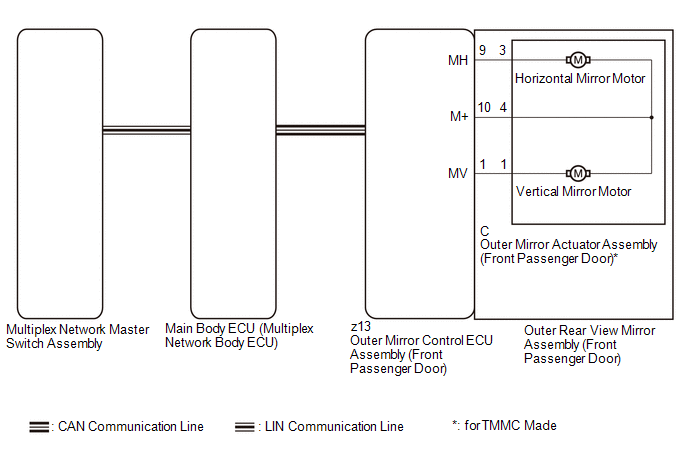
The multiplex network master switch assembly sends the mirror adjust switch signals to the main body ECU (multiplex network body ECU) via LIN communication. The main body ECU (multiplex network body ECU) then sends the received mirror adjust switch signals to the outer mirror control ECU assembly (front passenger door) via CAN communication. On receiving the signal, the outer mirror control ECU assembly (front passenger door) operates the vertical and horizontal mirror motors, which are built into the outer rear view mirror assembly (front passenger door), to adjust the mirror surface position.
WIRING DIAGRAM
CAUTION / NOTICE / HINT
NOTICE:
-
The power mirror control system (w/ Memory) uses the CAN communication system and LIN communication system. Inspect the communication functions by following How to Proceed with Troubleshooting. Troubleshoot the power window control system after confirming that the communication systems are functioning properly.
Click here
.gif)
-
Before replacing the main body ECU (multiplex network body ECU), refer to Registration.
Click here
PROCEDURE
| 1. | READ VALUE USING TECHSTREAM |
(a) Connect the Techstream to the DLC3.
(b) Turn the engine switch on (IG).
(c) Turn the Techstream on.
(d) Enter the following menus: Body Electrical / Master Switch / Data List.
(e) Read the Data List according to the display on the Techstream.
Body Electrical > Master Switch > Data List| Tester Display | Measurement Item | Range | Normal Condition | Diagnostic Note |
|---|---|---|---|---|
| Mirror Selection SW (R) | Mirror select switch signal for RH mirror | OFF or ON | OFF: Mirror select switch off ON: Mirror select switch R switch on | - |
| Mirror Position SW (L) | Mirror adjust switch signal (Left) | OFF or ON | OFF: Mirror adjust switch not pressed left ON: Mirror adjust switch pressed left | Check with the mirror select switch L or R switch on |
| Mirror Position SW (R) | Mirror adjust switch signal (Right) | OFF or ON | OFF: Mirror adjust switch not pressed right ON: Mirror adjust switch pressed right | Check with the mirror select switch L or R switch on |
| Mirror Position SW (Up) | Mirror adjust switch signal (Up) | OFF or ON | OFF: Mirror adjust switch not pressed up ON: Mirror adjust switch pressed up | Check with the mirror select switch L or R switch on |
| Mirror Position SW (Dwn) | Mirror adjust switch signal (Down) | OFF or ON | OFF: Mirror adjust switch not pressed down ON: Mirror adjust switch pressed down | Check with the mirror select switch L or R switch on |
| Tester Display |
|---|
| Mirror Selection SW (R) |
| Mirror Position SW (L) |
| Mirror Position SW (R) |
| Mirror Position SW (Up) |
| Mirror Position SW (Dwn) |
OK:
On the Techstream screen, ON or OFF is displayed accordingly.
| NG | .gif) | GO TO STEP 4 |
|
.gif)
| 2. | INSPECT OUTER REAR VIEW MIRROR ASSEMBLY (FRONT PASSENGER DOOR) (MIRROR SURFACE) |
(a) Remove the outer rear view mirror assembly (front passenger door).
Click here
(b) Inspect the outer rear view mirror assembly (front passenger door) (mirror surface).
Click here
| Result | Proceed to |
|---|---|
| OK | A |
| NG (ecxept TMMC Made) | B |
| NG (for TMMC Made) | C |
| A | | REPLACE OUTER MIRROR CONTROL ECU ASSEMBLY (FRONT PASSENGER DOOR) |
| B | | REPLACE OUTER REAR VIEW MIRROR ASSEMBLY (FRONT PASSENGER DOOR) |
|
| 3. | INSPECT OUTER REAR VIEW MIRROR ASSEMBLY (FRONT PASSENGER DOOR) (WIRE HARNESS) |
(a) Remove the outer mirror actuator assembly (front passenger door).
Click here
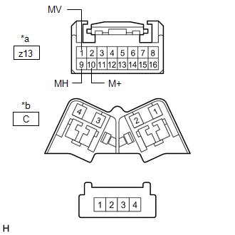
(b) Disconnect the z13 outer mirror control ECU assembly (front passenger door) connector.
| (c) Measure the resistance according to the value(s) in the table below. Standard Resistance:
|
|
| OK | | REPLACE OUTER MIRROR ACTUATOR ASSEMBLY (FRONT PASSENGER DOOR) |
| NG | | REPLACE OUTER REAR VIEW MIRROR ASSEMBLY (FRONT PASSENGER DOOR) |
| 4. | REPLACE MULTIPLEX NETWORK MASTER SWITCH ASSEMBLY |
(a) Temporarily replace the multiplex network master switch assembly with a new or known good one.
Click here
|
| 5. | CHECK POWER MIRROR CONTROL OPERATION |
(a) Check the electrical remote control mirror function.
Click here
OK:
Electrical remote control mirror function operates normally.
| OK | | END (MULTIPLEX NETWORK MASTER SWITCH ASSEMBLY WAS DEFECTIVE) |
| NG | | REPLACE MAIN BODY ECU (MULTIPLEX NETWORK BODY ECU) |
 Driver Side Power Mirror cannot be Adjusted with Power Mirror Switch
DESCRIPTION The multiplex network master switch assembly sends the mirror adjust switch signals to the main body ECU (multiplex network body ECU) via LIN communication. The main body ECU (multiplex ne ...
 Power Mirror cannot be Adjusted with Power Mirror Switch
DESCRIPTION The multiplex network master switch assembly sends the mirror adjust switch signals to the main body ECU (multiplex network body ECU) via LIN communication. The main body ECU (multiplex ne ...
Other materials:
Lexus RX (RX 350L, RX450h) 2016-2025 Repair Manual > Wireless Door Lock Control System: Customize Parameters
CUSTOMIZE PARAMETERS CUSTOMIZE WIRELESS DOOR LOCK CONTROL SYSTEM HINT: The following items can be customized. NOTICE:
When the customer requests a change in a function, first make sure that the function can be customized.
Be sure to make a note of the current settings before customizing.
When ...
Lexus RX (RX 350L, RX450h) 2016-2025 Owners Manual > Do-it-yourself
maintenance: Tires
Replace or rotate tires in accordance with maintenance schedules and
treadwear.
Checking tires
Check if the treadwear indicators are showing on the tires. Also check the
tires
for uneven wear, such as excessive wear on one side of the tread.
Check the spare tire condition and pressure if n ...
Lexus RX (RX 350L, RX450h) 2016-{YEAR} Owners Manual
- For your information
- Pictorial index
- For safety and security
- Instrument cluster
- Operation of each component
- Driving
- Lexus Display Audio system
- Interior features
- Maintenance and care
- When trouble arises
- Vehicle specifications
- For owners
Lexus RX (RX 350L, RX450h) 2016-{YEAR} Repair Manual

0.0168