Lexus RX (RX 350L, RX450h) 2016-2026 Repair Manual: Power Mirror Surface Position is not Memorized
DESCRIPTION
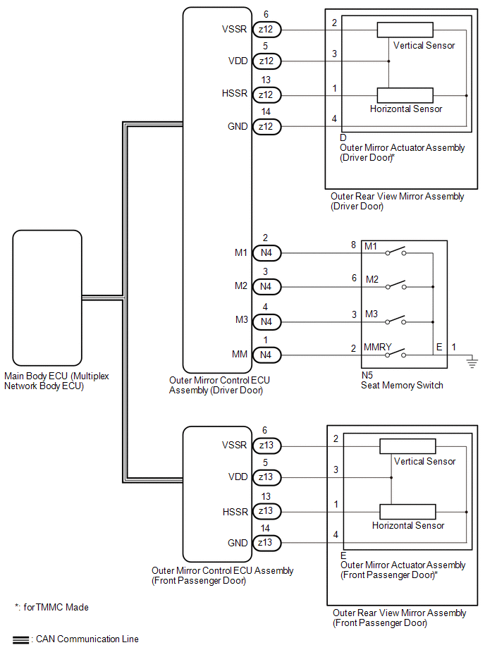
If any of the M1, M2 or M3 seat memory switch is pressed, the outer mirror control ECU assembly (driver door) detects the switch operation and sends the seat memory switch signal to the main body ECU (multiplex network body ECU) via CAN communication. On receiving the seat memory switch signal, the main body ECU (multiplex network body ECU) sends the memory request signal to each outer mirror control ECU assembly via CAN communication. When receiving this signal, each outer mirror control ECU assembly stores the mirror surface position based on information from the mirror position sensor, which is built into the outer rear view mirror assembly.
WIRING DIAGRAM
CAUTION / NOTICE / HINT
NOTICE:
-
The power mirror control system (w/ Memory) uses the CAN communication system. First, confirm that there is no malfunction in the CAN communication system. Refer to the How to Proceed with Troubleshooting procedure.
Click here
.gif)
-
Before replacing the main body ECU (multiplex network body ECU), refer to Registration.
Click here
- The mirror surface position will not be memorized if the engine switch is not on (IG).
- The mirror surface position will not be stored if the seat memory SET switch and 2 or more seat memory switches are pressed simultaneously.
- If the operation fails, the mirror surface position will not be memorized until the seat memory SET switch is released and the operation is attempted again.
- The mirror surface position will not be memorized when the mirror is operated manually.
HINT:
Each outer rear view mirror assembly has a built-in mirror vertical position sensor and mirror horizontal position sensor.
PROCEDURE
| 1. | READ VALUE USING TECHSTREAM |
(a) Connect the Techstream to the DLC3.
(b) Turn the engine switch on (IG).
(c) Turn the Techstream on.
(d) Enter the following menus: Body Electrical / Mirror L / Data List.
(e) Read the Data List according to the display on the Techstream.
Body Electrical > Mirror L > Data List| Tester Display | Measurement Item | Range | Normal Condition | Diagnostic Note |
|---|---|---|---|---|
| Seat Memory Switch1 | Seat memory switch M1 switch signal | OFF or ON | OFF: Seat memory switch M1 switch off ON: Seat memory switch M1 switch on | - |
| Seat Memory Switch2 | Seat memory switch M2 switch signal | OFF or ON | OFF: Seat memory switch M2 switch off ON: Seat memory switch M2 switch on | - |
| Seat Memory Switch3 | Seat memory switch M3 switch signal | OFF or ON | OFF: Seat memory switch M3 switch off ON: Seat memory switch M3 switch on | - |
| Seat Memory Set SW | Seat memory switch SET switch signal | OFF or ON | OFF: Seat memory switch SET switch off ON: Seat memory switch SET switch on | - |
| Tester Display |
|---|
| Seat Memory Switch1 |
| Seat Memory Switch2 |
| Seat Memory Switch3 |
| Seat Memory Set SW |
OK:
On the Techstream screen, ON or OFF is displayed accordingly.
| NG | .gif) | GO TO STEP 14 |
|
.gif)
| 2. | CHECK SEAT MEMORY SWITCH FUNCTION |
(a) When any seat memory switch (M1, M2 or M3) is pressed, check that the driver seat moves to the memorized position.
Click here
OK:
The driver seat moves to the memorized position.
| NG | | GO TO FRONT POWER SEAT CONTROL SYSTEM (Power Seat does not Return to Memorized Position) |
|
| 3. | CHECK MEMORY AND REACTIVATION FUNCTION |
| (a) Turn the engine switch on (IG). |
|
(b) Using the multiplex network master switch assembly, turn the mirror surface to the fully left position.
(c) Press the M1 switch while the SET switch is being pressed.
(d) Check that the buzzer sounds for 0.5 seconds and the mirror surface position is memorized.
(e) Using the multiplex network master switch assembly, turn the mirror surface to the fully right position.
(f) Press the M1 switch.
(g) Check that the buzzer sounds for 0.1 seconds and the outer mirror automatically moves to the memorized fully left position.
| Result | Proceed to |
|---|---|
| Memory and reactivation functions on both mirrors are not normal | A |
| Memory and reactivation functions on driver door mirror are not normal (ecxept TMMC Made) | B |
| Memory and reactivation functions on driver door mirror are not normal (for TMMC Made) | C |
| Memory and reactivation functions on front passenger door mirror are not normal (ecxept TMMC Made) | D |
| Memory and reactivation functions on front passenger door mirror are not normal (for TMMC Made) | E |
| A | | REPLACE MAIN BODY ECU (MULTIPLEX NETWORK BODY ECU) |
| C | | GO TO STEP 6 |
| D | | GO TO STEP 9 |
| E | | GO TO STEP 11 |
|
| 4. | REPLACE OUTER REAR VIEW MIRROR ASSEMBLY (DRIVER DOOR) |
(a) Temporarily replace the outer rear view mirror assembly (driver door) with a new or known good one.
Click here
|
| 5. | CHECK MEMORY AND REACTIVATION FUNCTION |
| (a) Turn the engine switch on (IG). |
|
(b) Using the multiplex network master switch assembly, turn the mirror surface to the fully left position.
(c) Press the M1 switch while the SET switch is being pressed.
(d) Check that the buzzer sounds for 0.5 seconds and the mirror surface position is memorized.
(e) Using the multiplex network master switch assembly, turn the mirror surface to the fully right position.
(f) Press the M1 switch.
(g) Check that the buzzer sounds for 0.1 seconds and the outer mirror automatically moves to the memorized fully left position.
| OK | | END (OUTER REAR VIEW MIRROR ASSEMBLY (DRIVER DOOR) WAS DEFECTIVE) |
| NG | | REPLACE OUTER MIRROR CONTROL ECU ASSEMBLY (DRIVER DOOR) |
| 6. | INSPECT OUTER REAR VIEW MIRROR ASSEMBLY (DRIVER DOOR) (WIRE HARNESS) |
(a) Remove the outer mirror actuator assembly (driver door).
Click here
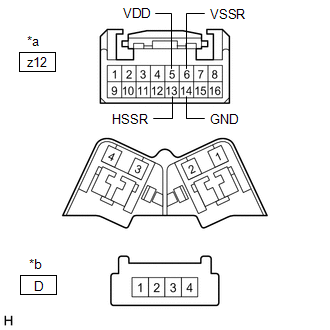
(b) Disconnect the z12 outer mirror control ECU assembly (driver door) connector.
| (c) Measure the resistance according to the value(s) in the table below. Standard Resistance:
|
|
| NG | | REPLACE OUTER REAR VIEW MIRROR ASSEMBLY (DRIVER DOOR) |
|
| 7. | REPLACE OUTER MIRROR ACTUATOR ASSEMBLY (DRIVER DOOR) |
(a) Temporarily replace the outer mirror actuator assembly (driver door) with a new or known good one.
Click here
|
| 8. | CHECK MEMORY AND REACTIVATION FUNCTION |
| (a) Turn the engine switch on (IG). |
|
(b) Using the multiplex network master switch assembly, turn the mirror surface to the fully left position.
(c) Press the M1 switch while the SET switch is being pressed.
(d) Check that the buzzer sounds for 0.5 seconds and the mirror surface position is memorized.
(e) Using the multiplex network master switch assembly, turn the mirror surface to the fully right position.
(f) Press the M1 switch.
(g) Check that the buzzer sounds for 0.1 seconds and the outer mirror automatically moves to the memorized fully left position.
| OK | | END (OUTER MIRROR ACTUATOR ASSEMBLY (DRIVER DOOR) WAS DEFECTIVE) |
| NG | | REPLACE OUTER MIRROR CONTROL ECU ASSEMBLY (DRIVER DOOR) |
| 9. | REPLACE OUTER REAR VIEW MIRROR ASSEMBLY (FRONT PASSENGER DOOR) |
(a) Temporarily replace the outer rear view mirror assembly (front passenger door) with a new or known good one.
Click here
|
| 10. | CHECK MEMORY AND REACTIVATION FUNCTION |
| (a) Turn the engine switch on (IG). |
|
(b) Using the multiplex network master switch assembly, turn the mirror surface to the fully left position.
(c) Press the M1 switch while the SET switch is being pressed.
(d) Check that the buzzer sounds for 0.5 seconds and the mirror surface position is memorized.
(e) Using the multiplex network master switch assembly, turn the mirror surface to the fully right position.
(f) Press the M1 switch.
(g) Check that the buzzer sounds for 0.1 seconds and the outer mirror automatically moves to the memorized fully left position.
| OK | | END (OUTER REAR VIEW MIRROR ASSEMBLY (FRONT PASSENGER DOOR) WAS DEFECTIVE) |
| NG | | REPLACE OUTER MIRROR CONTROL ECU ASSEMBLY (FRONT PASSENGER DOOR) |
| 11. | INSPECT OUTER REAR VIEW MIRROR ASSEMBLY (FRONT PASSENGER DOOR) (WIRE HARNESS) |
(a) Remove the outer mirror actuator assembly (front passenger door).
Click here
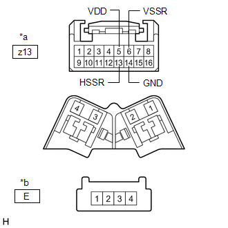
(b) Disconnect the z13 outer mirror control ECU assembly (front passenger door) connector.
| (c) Measure the resistance according to the value(s) in the table below. Standard Resistance:
|
|
| NG | | REPLACE OUTER REAR VIEW MIRROR ASSEMBLY (FRONT PASSENGER DOOR) |
|
| 12. | REPLACE OUTER MIRROR ACTUATOR ASSEMBLY (FRONT PASSENGER DOOR) |
(a) Temporarily replace the outer mirror actuator assembly (front passenger door) with a new or known good one.
Click here
|
| 13. | CHECK MEMORY AND REACTIVATION FUNCTION |
| (a) Turn the engine switch on (IG). |
|
(b) Using the multiplex network master switch assembly, turn the mirror surface to the fully left position.
(c) Press the M1 switch while the SET switch is being pressed.
(d) Check that the buzzer sounds for 0.5 seconds and the mirror surface position is memorized.
(e) Using the multiplex network master switch assembly, turn the mirror surface to the fully right position.
(f) Press the M1 switch.
(g) Check that the buzzer sounds for 0.1 seconds and the outer mirror automatically moves to the memorized fully left position.
| OK | | END (OUTER MIRROR ACTUATOR ASSEMBLY (FRONT PASSENGER DOOR) WAS DEFECTIVE) |
| NG | | REPLACE OUTER MIRROR CONTROL ECU ASSEMBLY (FRONT PASSENGER DOOR) |
| 14. | INSPECT SEAT MEMORY SWITCH |
(a) Remove the seat memory switch (driver door).
Click here
(b) Inspect the seat memory switch (driver door).
Click here
| NG | | REPLACE SEAT MEMORY SWITCH |
|
| 15. | CHECK HARNESS AND CONNECTOR (SEAT MEMORY SWITCH - OUTER MIRROR CONTROL ECU ASSEMBLY (DRIVER DOOR) - BODY GROUND) |
(a) Disconnect the N4 outer mirror control ECU assembly (driver door) connector.
(b) Disconnect the N5 seat memory switch connector.
(c) Measure the resistance according to the value(s) in the table below.
Standard Resistance:
| Tester Connection | Condition | Specified Condition |
|---|---|---|
| N4-1 (MM) - N5-2 (MMRY) | Always | Below 1 Ω |
| N4-1 (MM) or N5-2 (MMRY) - Body ground | Always | 10 kΩ or higher |
| N4-2 (M1) - N5-8 (M1) | Always | Below 1 Ω |
| N4-2 (M1) or N5-8 (M1) - Body ground | Always | 10 kΩ or higher |
| N4-3 (M2) - N5-6 (M2) | Always | Below 1 Ω |
| N4-3 (M2) or N5-6 (M2) - Body ground | Always | 10 kΩ or higher |
| N4-4 (M3) - N5-3 (M3) | Always | Below 1 Ω |
| N4-4 (M3) or N5-3 (M3) - Body ground | Always | 10 kΩ or higher |
| N5-1 (E) - Body ground | Always | Below 1 Ω |
| OK | | REPLACE OUTER MIRROR CONTROL ECU ASSEMBLY (DRIVER DOOR) |
| NG | | REPAIR OR REPLACE HARNESS OR CONNECTOR |
 AUTO Power Retract Mirrors do not operate
DESCRIPTION The multiplex network master switch assembly sends the auto retractable outer mirror switch signal to the main body ECU (multiplex network body ECU) via LIN communication. The main body EC ...
 Power Mirrors do not Return to Memorized Position
DESCRIPTION If any of the M1, M2 or M3 seat memory switch is pressed, the outer mirror control ECU assembly (driver door) detects the switch operation and sends the seat memory switch signal to the ma ...
Other materials:
Lexus RX (RX 350L, RX450h) 2016-2026 Repair Manual > Intake Manifold: Installation
INSTALLATION PROCEDURE 1. INSTALL STUD BOLT HINT: If a stud bolt is deformed or the threads are damaged, replace it. (a) Using an E8 "TORX" socket wrench, install the 2 stud bolts to the intake manifold. Torque: 10 N·m {102 kgf·cm, 7 ft·lbf} 2. INSTALL NO. 1 INTAKE MANIFOLD TO HEA ...
Lexus RX (RX 350L, RX450h) 2016-2026 Repair Manual > Audio And Visual System (for 8 Inch Display): Portable Player cannot be Operated Using In-vehicle Device or Track Information is not Displayed on In-vehicle Device
PROCEDURE 1. CHECK USING ANOTHER "Bluetooth" AUDIO COMPATIBLE VEHICLE OF SAME MODEL (a) Check if track information is displayed normally on another "Bluetooth" audio compatible vehicle of the same model. OK: Track information is displayed normally. OK PROCEED TO NEXT SUSPECTED AREA ...
Lexus RX (RX 350L, RX450h) 2016-{YEAR} Owners Manual
- For your information
- Pictorial index
- For safety and security
- Instrument cluster
- Operation of each component
- Driving
- Lexus Display Audio system
- Interior features
- Maintenance and care
- When trouble arises
- Vehicle specifications
- For owners
Lexus RX (RX 350L, RX450h) 2016-{YEAR} Repair Manual

0.012