Lexus RX (RX 350L, RX450h) 2016-2026 Repair Manual: Installation
INSTALLATION
PROCEDURE
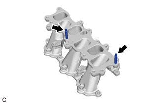
1. INSTALL STUD BOLT
HINT:
If a stud bolt is deformed or the threads are damaged, replace it.
| (a) Using an E8 "TORX" socket wrench, install the 2 stud bolts to the intake manifold. Torque: 10 N·m {102 kgf·cm, 7 ft·lbf} |
|
2. INSTALL NO. 1 INTAKE MANIFOLD TO HEAD GASKET
(a) Install 2 new No. 1 intake manifold to head gaskets to each cylinder head sub-assembly.
NOTICE:
- Align the port holes of the No. 1 intake manifold to head gaskets and cylinder head sub-assembly.
- Make sure that the No. 1 intake manifold to head gaskets are installed in the correct direction.
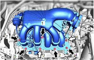
3. INSTALL INTAKE MANIFOLD
(a) Temporarily install the intake manifold to the cylinder head sub-assembly with the 4 bolts and 4 nuts.
(b) Tighten the 4 bolts and 4 nuts in the order shown in the illustration.
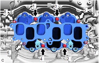
.png) | Bolt |
.png) | Nut |
Torque:
21 N·m {214 kgf·cm, 15 ft·lbf}
4. INSTALL INJECTOR VIBRATION INSULATOR
Click here .gif)
5. INSTALL NO. 1 DELIVERY PIPE SPACER
Click here
6. INSTALL FUEL DELIVERY PIPE SUB-ASSEMBLY
Click here
7. CONNECT FUEL TUBE SUB-ASSEMBLY
Click here
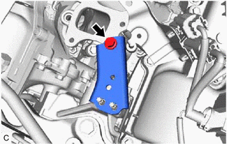
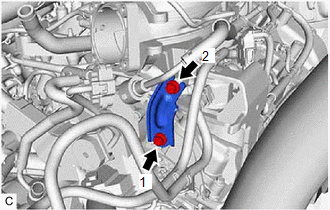
8. INSTALL NO. 2 ENGINE MOUNTING STAY RH
| (a) Install the No. 2 engine mounting stay RH to the intake manifold with the bolt. Torque: 21 N·m {214 kgf·cm, 15 ft·lbf} |
|
(b) Connect the wire harness clamp bracket to the No. 2 engine mounting stay RH with the bolt.
Torque:
10 N·m {102 kgf·cm, 7 ft·lbf}
(c) Engage the wire harness clamp to the wire harness clamp bracket.
(d) Install the No. 2 engine mounting stay RH to the engine mounting insulator sub-assembly RH with the bolt and 2 nuts.
Torque:
20 N·m {204 kgf·cm, 15 ft·lbf}
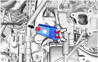
| | Bolt |
| | Nut |
9. INSTALL NO. 1 V-BANK COVER BRACKET
HINT:
Perform this procedure only when replacement of the No. 1 V-bank cover bracket is necessary.
(a) Install the 2 No. 1 V-bank cover brackets to the intake air surge tank assembly.
Torque:
9.0 N·m {92 kgf·cm, 80 in·lbf}
10. INSTALL AIR SURGE TANK TO INTAKE MANIFOLD GASKET
(a) Install a new air surge tank to intake manifold gasket to the intake air surge tank assembly.
11. INSTALL INTAKE AIR SURGE TANK ASSEMBLY
NOTICE:
Do not apply oil to the bolts and nuts as listed below:
| Oil Application Prohibited Bolt and Nut |
|---|
| Bolt and Nut for Intake Air Surge Tank Assembly and Intake Manifold |
| Bolt for No. 2 Surge Tank Stay and Intake Air Surge Tank Assembly |
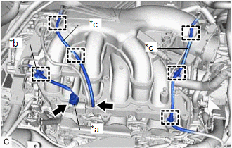
(a) Connect the vacuum hose sub-assembly to the intake air surge tank assembly.
(b) Temporarily install the intake air surge tank assembly to the intake manifold with the 5 bolts and 2 nuts.
(c) Temporarily install the No. 2 surge tank stay to the intake manifold and camshaft housing RH with the 2 bolts.
(d) Tighten the 5 bolts and 2 nuts in the order shown in the illustration.
Torque:
21 N·m {214 kgf·cm, 15 ft·lbf}
| | Bolt |
| | Nut |
| (e) Tighten the 2 bolts in the order shown in the illustration. Torque: 21 N·m {214 kgf·cm, 15 ft·lbf} |
|
| (f) Engage the clamp to connect the No. 2 air tube to the intake air surge tank assembly. |
|

(g) Engage the 2 clamps to connect the vacuum hose sub-assembly to the intake air surge tank assembly.
| (h) Engage the 5 clamps to connect the vacuum hose sub-assembly to the intake air surge tank assembly. |
|
(i) Engage the wire harness clamp to the intake air surge tank assembly.
(j) Connect the vacuum switching valve (for ACIS) connector.
12. CONNECT PURGE VALVE (PURGE VSV)
(a) Connect the purge valve (purge VSV) to the intake air surge tank assembly with the bolt.
Torque:
21 N·m {214 kgf·cm, 15 ft·lbf}
(b) Connect the No. 1 fuel vapor feed hose to the intake air surge tank assembly.
13. CONNECT VENTILATION HOSE
(a) Connect the ventilation hose to the intake air surge tank assembly and slide the clip to secure it.
14. INSTALL THROTTLE BODY WITH MOTOR ASSEMBLY
Click here
15. CONNECT CABLE TO NEGATIVE BATTERY TERMINAL
NOTICE:
When disconnecting the cable, some systems need to be initialized after the cable is reconnected.
Click here
16. INSPECT FOR FUEL LEAK
Click here
17. INSTALL V-BANK COVER SUB-ASSEMBLY
Click here
 Components
COMPONENTS ILLUSTRATION *A for TMMC Made *B except TMMC Made *1 VENTILATION HOSE *2 PURGE VALVE (PURGE VSV) *3 NO. 1 FUEL VAPOR FEED HOSE *4 NO. 2 SURGE TANK STAY *5 ...
 Removal
REMOVAL CAUTION / NOTICE / HINT The necessary procedures (adjustment, calibration, initialization or registration) that must be performed after parts are removed and installed, or replaced during inta ...
Other materials:
Lexus RX (RX 350L, RX450h) 2016-2026 Repair Manual > Rear Combination Light Assembly (w/ Rear No. 2 Seat): Reassembly
REASSEMBLY CAUTION / NOTICE / HINT HINT:
Use the same procedure for the RH side and LH side.
The following procedure is for the LH side.
PROCEDURE 1. INSTALL REAR COMBINATION LIGHT LENS AND BODY (for Bulb Type Turn Signal Light) 2. INSTALL REAR COMBINATION LIGHT BRACKET (for Bulb Type Turn S ...
Lexus RX (RX 350L, RX450h) 2016-2026 Repair Manual > Front Camera: Before Starting Adjustment
BEFORE STARTING ADJUSTMENT CAUTION / NOTICE / HINT NOTICE: When replacing the windshield glass of a vehicle equipped with a forward recognition camera, make sure to use a Toyota genuine part. If a non-Toyota genuine part is used, the forward recognition camera may not be able to be installed due to ...
Lexus RX (RX 350L, RX450h) 2016-{YEAR} Owners Manual
- For your information
- Pictorial index
- For safety and security
- Instrument cluster
- Operation of each component
- Driving
- Lexus Display Audio system
- Interior features
- Maintenance and care
- When trouble arises
- Vehicle specifications
- For owners
Lexus RX (RX 350L, RX450h) 2016-{YEAR} Repair Manual

0.0101