Lexus RX (RX 350L, RX450h) 2016-2026 Repair Manual: Removal
REMOVAL
CAUTION / NOTICE / HINT
The necessary procedures (adjustment, calibration, initialization or registration) that must be performed after parts are removed and installed, or replaced during intake manifold removal/installation are shown below.
Necessary Procedures After Parts Removed/Installed/Replaced| Replaced Part or Performed Procedure | Necessary Procedure | Effect/Inoperative Function when Necessary Procedure not Performed | Link |
|---|---|---|---|
|
*1: When performing learning using the Techstream.
Click here | |||
| Battery terminal is disconnected/reconnected | Memorize steering angle neutral point | Lane Control System | |
| Pre-collision System | |||
| Intelligent Clearance Sonar System*1 | |||
| Lighting System (w/ Automatic Headlight Beam Level Control System) | | ||
| Parking Assist Monitor System | | ||
| Panoramic View Monitor System | | ||
| Initialize back door lock | Power Door Lock Control System | | |
| Reset back door close position | Power Back Door System (w/ Outside Door Control Switch) | | |
| Inspection After Repair |
| |
NOTICE:
After the engine switch is turned off, the radio receiver assembly records various types of memory and settings. As a result, after turning the engine switch off, make sure to wait at least 120 seconds before disconnecting the cable from the negative (-) battery terminal.
PROCEDURE
1. PRECAUTION
NOTICE:
After turning the engine switch off, waiting time may be required before disconnecting the cable from the negative (-) battery terminal. Therefore, make sure to read the disconnecting the cable from the negative (-) battery terminal notices before proceeding with work.
Click here .gif)
2. DISCHARGE FUEL SYSTEM PRESSURE
Click here
3. DISCONNECT CABLE FROM NEGATIVE BATTERY TERMINAL
NOTICE:
When disconnecting the cable, some systems need to be initialized after the cable is reconnected.
Click here
4. REMOVE THROTTLE BODY WITH MOTOR ASSEMBLY
Click here
5. REMOVE V-BANK COVER SUB-ASSEMBLY
Click here
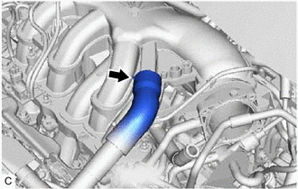
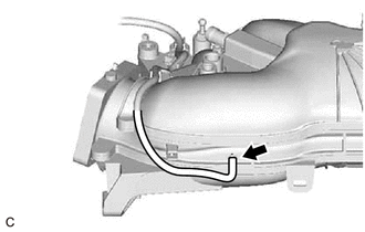
6. DISCONNECT VENTILATION HOSE
| (a) Slide the clip and disconnect the ventilation hose from the intake air surge tank assembly. |
|
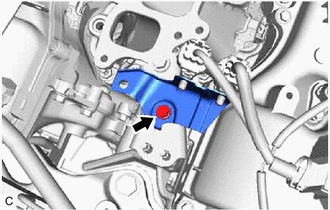
7. DISCONNECT PURGE VALVE (PURGE VSV) (for TMMC Made)
| (a) Disconnect the No. 1 fuel vapor feed hose from the intake air surge tank assembly. |
|
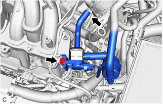
(b) Remove the bolt and disconnect the purge valve (purge VSV) from the intake air surge tank assembly.
8. DISCONNECT PURGE VALVE (PURGE VSV) (except TMMC Made)
| (a) Disconnect the No. 1 fuel vapor feed hose from the intake air surge tank assembly. |
|
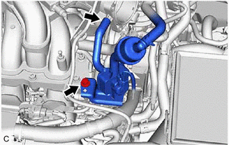
(b) Remove the bolt and disconnect the purge valve (purge VSV) from the intake air surge tank assembly.
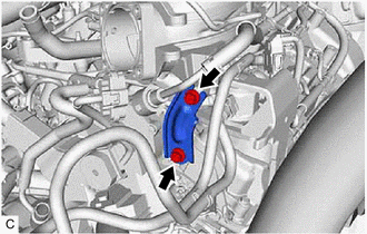
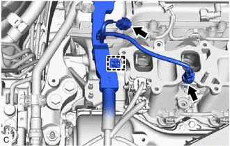
9. REMOVE NO. 2 SURGE TANK STAY
| (a) Remove the 2 bolts and No. 2 surge tank stay from the intake manifold and camshaft housing RH. |
|
10. REMOVE INTAKE AIR SURGE TANK ASSEMBLY
| (a) Disconnect the vacuum switching valve (for ACIS) connector. |
|
.png)
(b) Disengage the wire harness clamp from the intake air surge tank assembly.
(c) Disengage the 5 clamps to disconnect the vacuum hose sub-assembly from the intake air surge tank assembly.
| (d) Disengage the 2 clamps to disconnect the vacuum hose sub-assembly from the intake air surge tank assembly. |
|
.png)
(e) Disengage the clamp to disconnect the No. 2 air tube from the intake air surge tank assembly.
(f) Remove the 5 bolts, 2 nuts and intake air surge tank assembly from the intake manifold.
.png) | Bolt |
.png) | Nut |
| (g) Disconnect the vacuum hose sub-assembly from the intake air surge tank assembly. |
|
11. REMOVE AIR SURGE TANK TO INTAKE MANIFOLD GASKET
| (a) Remove the air surge tank to intake manifold gasket from the intake air surge tank assembly. |
|
12. REMOVE NO. 1 V-BANK COVER BRACKET
HINT:
Perform this procedure only when replacement of the No. 1 V-bank cover bracket is necessary.
| (a) Remove the 2 No. 1 V-bank cover brackets from the intake air surge tank assembly. |
|
13. REMOVE NO. 2 ENGINE MOUNTING STAY RH
.png)
| | Bolt |
| | Nut |
(a) Remove the bolt, 2 nuts and No. 2 engine mounting stay RH from the engine mounting insulator sub-assembly RH.
| (b) Disengage the wire harness clamp from the wire harness clamp bracket. |
|
| (c) Remove the bolt and disconnect the wire harness clamp bracket from the No. 2 engine mounting stay RH. |
|
| (d) Remove the bolt and No. 2 engine mounting stay RH from the intake manifold and engine mounting insulator sub-assembly RH. |
|
.png)
14. DISCONNECT FUEL TUBE SUB-ASSEMBLY
Click here
15. REMOVE FUEL DELIVERY PIPE SUB-ASSEMBLY
Click here
16. REMOVE NO. 1 DELIVERY PIPE SPACER
Click here
17. REMOVE INJECTOR VIBRATION INSULATOR
Click here
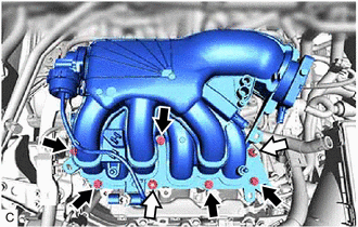
18. REMOVE INTAKE MANIFOLD
(a) Remove the 4 bolts, 4 nuts and intake manifold from the cylinder head sub-assembly.
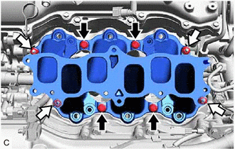
| | Bolt |
| | Nut |
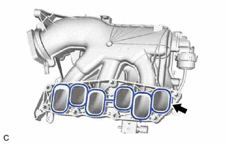
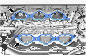
19. REMOVE NO. 1 INTAKE MANIFOLD TO HEAD GASKET
| (a) Remove the 2 No. 1 intake manifold to head gaskets from each cylinder head sub-assembly. |
|
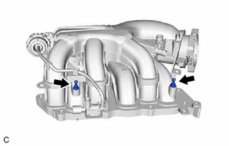
20. REMOVE STUD BOLT
HINT:
If a stud bolt is deformed or the threads are damaged, replace it.
| (a) Using an E8 "TORX" socket wrench, remove the 2 stud bolts from the intake manifold. |
|
.png)
 Installation
INSTALLATION PROCEDURE 1. INSTALL STUD BOLT HINT: If a stud bolt is deformed or the threads are damaged, replace it. (a) Using an E8 "TORX" socket wrench, install the 2 stud bolts to the intake man ...
 Intake System
...
Other materials:
Lexus RX (RX 350L, RX450h) 2016-2026 Repair Manual > Power Steering System: On-vehicle Inspection
ON-VEHICLE INSPECTION PROCEDURE 1. CHECK STEERING EFFORT (TORQUE) NOTICE: These service operations may affect the SRS airbags. Be sure to read the precautionary notices concerning the SRS airbag system before servicing. Click here (a) Stop the vehicle on a level, paved surface and align the whe ...
Lexus RX (RX 350L, RX450h) 2016-2026 Repair Manual > Can Communication System: System Diagram
SYSTEM DIAGRAM (a) The CAN communication system is composed of 7 buses. CAN Main Bus Line Terminating Resistor CAN Branch Line * Gateway Function Equipped ECU Bus Monitored Direction - - CAN Main Bus Line Terminating Resistor CAN Branch Line ...
Lexus RX (RX 350L, RX450h) 2016-{YEAR} Owners Manual
- For your information
- Pictorial index
- For safety and security
- Instrument cluster
- Operation of each component
- Driving
- Lexus Display Audio system
- Interior features
- Maintenance and care
- When trouble arises
- Vehicle specifications
- For owners
Lexus RX (RX 350L, RX450h) 2016-{YEAR} Repair Manual

0.0088