Lexus RX (RX 350L, RX450h) 2016-2026 Repair Manual: System Diagram
SYSTEM DIAGRAM
(a) The CAN communication system is composed of 7 buses.

 | CAN Main Bus Line |  | Terminating Resistor |
 | CAN Branch Line | * | Gateway Function Equipped ECU |
.png) | Bus Monitored Direction | - | - |
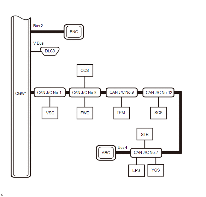
| | CAN Main Bus Line | | Terminating Resistor |
| | CAN Branch Line | * | Gateway Function Equipped ECU |
| Bus | Code | ECU/Sensor Name | CAN DTC Storage | Note |
|---|---|---|---|---|
| - | CGW | Network Gateway ECU | - | - |
| V Bus | DLC3 | DLC3 | - | - |
| Bus 1 | MAV | Parking Assist ECU | Available | w/ Panoramic View Monitor System |
| CSR | Clearance Warning ECU Assembly | Available | w/ Intuitive Parking Assist System | |
| FCM | Forward Recognition Camera | Available | - | |
| FRD | Millimeter Wave Radar Sensor Assembly | Available | - | |
| CAA | Rear Television Camera Assembly | - | w/ Panoramic View Monitor System | |
| Available | w/ Parking Assist Monitor System | |||
| BSR | Blind Spot Monitor Sensor LH | Available | w/ Blind Spot Monitor System | |
| CAN J/C No.3 | No. 3 CAN Junction Connector | - | - | |
| CAN J/C No.10 | No. 10 CAN Junction Connector | - | - | |
| Bus 2 | ENG | ECM | Available | - |
| Bus 3 | AVN | Radio Receiver Assembly | Available | - |
| DCM | DCM (Telematics Transceiver) | Available | w/ Manual (SOS) Switch | |
| CAN J/C No.6 | No. 6 CAN Junction Connector | - | - | |
| Bus 4 | VSC | Skid Control ECU (Brake Actuator Assembly) | Available | - |
| FWD | 4WD ECU ASSEMBLY | Available | for AWD | |
| ODS | Occupant Detection ECU | - | - | |
| EPS | Power Steering ECU Assembly | Available | - | |
| STR | Steering Sensor | - | - | |
| YGS | Yaw Rate Sensor Assembly | - | w/ TFT Meter Type Combination Meter Assembly | |
| ABG | Airbag Sensor Assembly | Available | - | |
| TPM | Tire Pressure Warning ECU and Receiver | Available | - | |
| SCS | Absorber Control ECU | Available | w/ AVS | |
| CAN J/C No.1 | No. 1 CAN Junction Connector | - | - | |
| CAN J/C No.7 | No. 7 CAN Junction Connector | - | - | |
| CAN J/C No.8 | No. 8 CAN Junction Connector | - | - | |
| CAN J/C No.9 | No. 9 CAN Junction Connector | - | - | |
| CAN J/C No.12 | No. 12 CAN Junction Connector | - | - | |
| Bus 5 | ACN | Air Conditioning Amplifier Assembly | Available | - |
| MET | Combination Meter Assembly | Available | - | |
| IDT | Certification ECU (Smart Key ECU Assembly) | Available | - | |
| BDB | Main Body ECU (Multiplex Network Body ECU) | Available |
| |
| AFS | Headlight ECU Sub-assembly LH | Available | w/ Automatic Headlight Beam Level Control System | |
| HUD | Combination Meter Mirror ECU (Headup Display) | Available | w/ Headup Display System | |
| CAN J/C No.5 | No. 5 CAN Junction Connector | - | - | |
| Sub Bus 1 | BDB | Main Body ECU (Multiplex Network Body ECU) | Available |
|
| BKD | Multiplex Network Door ECU | Available | - | |
| DFL | Outer Mirror Control ECU Assembly (for Driver Side) | Available | - | |
| TAT | Multiplex Tilt and Telescopic ECU | Available | - | |
| DST | Position Control ECU and Switch Assembly LH | - | w/ Seat Position Memory System | |
| DFR | Outer Mirror Control ECU Assembly (for Front Passenger Side) | Available | - | |
| ST1 | No. 1 CAN Junction Terminal | - | - | |
| CAN J/C No.11 | No. 11 CAN Junction Connector | - | - | |
| CAN J/C No.8 | No. 8 CAN Junction Connector | - | - |
 Precaution
PRECAUTION NOTICE FOR INITIALIZATION NOTICE: When disconnecting the cable from the negative (-) battery terminal, initialize the following systems after the cable is reconnected. System See Proce ...
 System Description
SYSTEM DESCRIPTION BRIEF DESCRIPTION (a) The Controller Area Network (CAN) is a serial data communication system for real time application. It is a vehicle multiplex communication system which has a h ...
Other materials:
Lexus RX (RX 350L, RX450h) 2016-2026 Repair Manual > Steering Lock System: Diagnosis System
DIAGNOSIS SYSTEM DESCRIPTION (a) The steering lock ECU (steering lock actuator or upper bracket assembly) stores DTCs when a malfunction occurs in the system. These DTCs can be confirmed by using the Techstream. NOTICE:
When using the Techstream with the engine switch off to confirm DTCs or Data ...
Lexus RX (RX 350L, RX450h) 2016-2026 Repair Manual > Air Conditioning System: Rear Blower Motor Circuit
DESCRIPTION The rear blower motor with fan sub-assembly is operated by signals from the air conditioning amplifier assembly. Rear blower motor speed signals are transmitted in accordance with changes in the duty ratio. WIRING DIAGRAM CAUTION / NOTICE / HINT NOTICE: Inspect the fuses for circuits re ...
Lexus RX (RX 350L, RX450h) 2016-{YEAR} Owners Manual
- For your information
- Pictorial index
- For safety and security
- Instrument cluster
- Operation of each component
- Driving
- Lexus Display Audio system
- Interior features
- Maintenance and care
- When trouble arises
- Vehicle specifications
- For owners
Lexus RX (RX 350L, RX450h) 2016-{YEAR} Repair Manual

0.0099