Lexus RX (RX 350L, RX450h) 2016-2026 Repair Manual: Installation
INSTALLATION
PROCEDURE
1. INSTALL FUEL PIPE PLUG SUB-ASSEMBLY
(a) Install a new O-ring, new No. 1 fuel injector back-up ring, new No. 2 fuel injector back-up ring and new No. 3 fuel injector back-up ring to the fuel pipe plug sub-assembly as shown in the illustration.
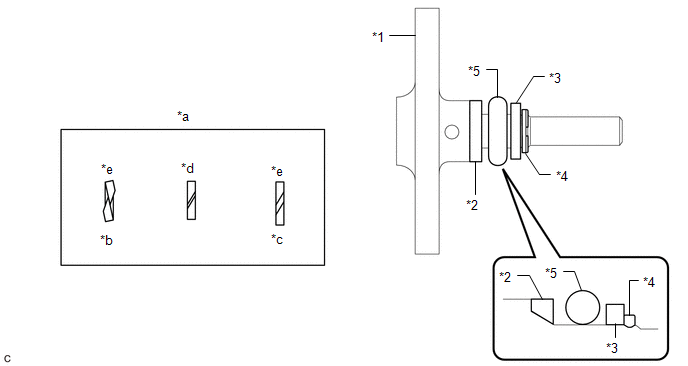
| *1 | Fuel Pipe Plug Sub-assembly | *2 | No. 1 Fuel Injector Back-up Ring |
| *3 | No. 2 Fuel Injector Back-up Ring | *4 | No. 3 Fuel Injector Back-up Ring |
| *5 | O-ring | - | - |
| *a | Opening | *b | Overlapped |
| *c | Stretched | *d | Correct |
| *e | Incorrect | - | - |
NOTICE:
- Check that there is no foreign matter or damage on the O-ring groove of the fuel pipe plug sub-assembly.
- Check that the No. 1 fuel injector back-up ring and No. 3 fuel injector back-up ring are installed in the correct orientation.
- Make sure that the No. 1 fuel injector back-up ring, No. 2 fuel injector back-up ring, No. 3 fuel injector back-up ring and O-ring are installed in the correct order.
- Check that the opening of the No. 1 fuel injector back-up ring is not overlapped or stretched as shown in the illustration.
- After installing the O-ring, check that it is not contaminated with foreign matter and is not damaged.
(b) w/ Dust Cap:
(1) Install the dust cap sub-assembly to the fuel pipe plug sub-assembly.
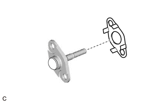
| (c) Install a new gasket to the fuel pipe plug sub-assembly as shown in the illustration. |
|
(d) Secure the fuel delivery pipe with sensor assembly LH in a vise between aluminum plates.
NOTICE:
Do not overtighten the vise.
(e) Using a 5 mm hexagon socket wrench, install the fuel pipe plug sub-assembly to the fuel delivery pipe with sensor assembly LH with the 2 bolts.
Torque:
10 N·m {102 kgf·cm, 7 ft·lbf}
(f) Remove the fuel delivery pipe with sensor assembly LH from the vise.
2. INSTALL FUEL DELIVERY PIPE WITH SENSOR ASSEMBLY LH (FUEL PRESSURE SENSOR)
HINT:
Perform "Inspection After Repair" after replacing the fuel delivery pipe with sensor assembly LH (fuel pressure sensor).
Click here .gif)
Click here
NOTICE:
- Do not remove the fuel pressure sensor from the fuel delivery pipe with sensor assembly LH.
- If the fuel pressure sensor is removed, replace the fuel delivery pipe with sensor assembly LH (fuel pressure sensor) with a new one.
3. PERFORM INITIALIZATION
(a) Perform "Inspection After Repair" after replacing the fuel delivery pipe with sensor assembly LH (fuel pressure sensor).
Click here
 Inspection
INSPECTION PROCEDURE 1. INSPECT FUEL DELIVERY PIPE WITH SENSOR ASSEMBLY LH (FUEL PRESSURE SENSOR) NOTICE:
Do not remove the fuel pressure sensor from the fuel delivery pipe with sensor assembly LH. ...

Other materials:
Lexus RX (RX 350L, RX450h) 2016-2026 Repair Manual > Audio And Visual System (for 12.3 Inch Display): Precaution
PRECAUTION PRECAUTION FOR DISCONNECTING CABLE FROM NEGATIVE BATTERY TERMINAL NOTICE:
After the engine switch is turned off, the radio receiver assembly records various types of memory and settings. As a result, after turning the engine switch off, make sure to wait at least 120 seconds before dis ...
Lexus RX (RX 350L, RX450h) 2016-2026 Repair Manual > Automatic Transaxle Assembly: Removal
REMOVAL CAUTION / NOTICE / HINT The necessary procedures (adjustment, calibration, initialization or registration) that must be performed after parts are removed and installed, or replaced during automatic transaxle assembly removal/installation are shown below. Necessary Procedure After Parts Remov ...
Lexus RX (RX 350L, RX450h) 2016-{YEAR} Owners Manual
- For your information
- Pictorial index
- For safety and security
- Instrument cluster
- Operation of each component
- Driving
- Lexus Display Audio system
- Interior features
- Maintenance and care
- When trouble arises
- Vehicle specifications
- For owners
Lexus RX (RX 350L, RX450h) 2016-{YEAR} Repair Manual

0.0115