Lexus RX (RX 350L, RX450h) 2016-2026 Repair Manual: Removal
REMOVAL
CAUTION / NOTICE / HINT
The necessary procedures (adjustment, calibration, initialization, or registration) that must be performed after parts are removed, installed, or replaced during the steering vibration and heater ECU removal/installation are shown below.
Necessary Procedure After Parts Removed/Installed/Replaced| Replacement Part or Procedure | Necessary Procedures | Effects / Inoperative when not performed | Link |
|---|---|---|---|
|
*1: When performing learning using the Techstream.
Click here | |||
| Disconnect cable from negative battery terminal | Memorize steering angle neutral point | Lane Control System | |
| Pre-collision system | |||
| Intelligent clearance sonar system*1 | |||
| Lighting system (w/ Automatic Headlight Beam Level Control System) | | ||
| Parking assist monitor system | | ||
| Panoramic view monitor system | | ||
| Initialize back door lock | Power door lock control system | | |
| Reset back door close position | Power Back Door System (w/ Outside Door Control Switch) | | |
PROCEDURE
1. REMOVE STEERING WHEEL ASSEMBLY
Click here .gif)
2. REMOVE CRUISE CONTROL MAIN SWITCH
Click here
3. REMOVE STEERING PAD SWITCH ASSEMBLY
Click here
4. REMOVE SHIFT PADDLE SWITCH (TRANSMISSION SHIFT SWITCH ASSEMBLY)
for U881F: Click here
for U881E: Click here
5. REMOVE STEERING VIBRATION AND HEATER ECU
| (a) Disengage the guide to remove the wire harness from the lower steering wheel cover. |
|
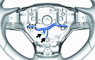
(b) Disconnect each connector.
| (c) Remove the screw. |
|
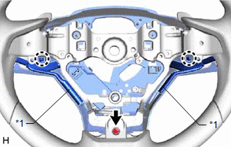
(d) Disengage the 2 claws of the lower steering wheel boss cover.
NOTICE:
If the heater thermistor comes off the lower steering wheel cover, replace the steering wheel assembly.
HINT:
Do not remove the lower steering wheel boss cover from the steering wheel sub-assembly. Loosen the lower steering boss cover.
(e) Remove the 2 screws.
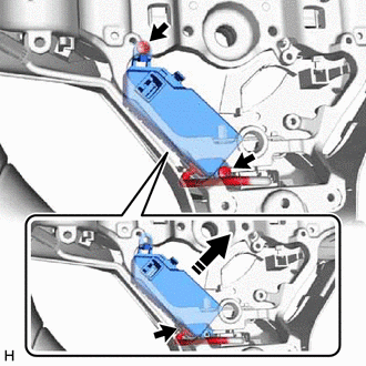
 | Remove in this Direction |
(f) Move the steering vibration and heater ECU until it reaches a position where the connector can be disconnected.
(g) Disconnect the connector to remove the steering vibration and heater ECU from the lower steering wheel cover.
 Installation
INSTALLATION PROCEDURE 1. INSTALL STEERING VIBRATION AND HEATER ECU (a) Connect the connector to the steering vibration and heater ECU. (b) Install the steering vibration and heater ECU to the lower s ...

Other materials:
Lexus RX (RX 350L, RX450h) 2016-2026 Repair Manual > Front Airbag Sensor: Components
COMPONENTS ILLUSTRATION *1 FRONT AIRBAG SENSOR *2 FRONT FENDER REINFORCEMENT SUB-ASSEMBLY TOP *3 HEADLIGHT ASSEMBLY *4 CENTER HOOD CUSHION Tightening torque for "Major areas involving basic vehicle performance such as moving/turning/stopping" : N*m (kgf*cm, ft.*lbf) N ...
Lexus RX (RX 350L, RX450h) 2016-2026 Repair Manual > Steering Column Assembly: Reassembly
REASSEMBLY CAUTION / NOTICE / HINT NOTICE:
Do not drop the power steering ECU assembly, strike it with tools or subject it to impacts.
If the power steering ECU assembly is subjected to an impact, replace it with a new one.
Do not pull the wire harness.
Do not allow any moisture to come int ...
Lexus RX (RX 350L, RX450h) 2016-{YEAR} Owners Manual
- For your information
- Pictorial index
- For safety and security
- Instrument cluster
- Operation of each component
- Driving
- Lexus Display Audio system
- Interior features
- Maintenance and care
- When trouble arises
- Vehicle specifications
- For owners
Lexus RX (RX 350L, RX450h) 2016-{YEAR} Repair Manual

0.0139