Lexus RX (RX 350L, RX450h) 2016-2026 Repair Manual: System Description
SYSTEM DESCRIPTION
BRIEF DESCRIPTION
(a) The Controller Area Network (CAN) is a serial data communication system for real time application. It is a vehicle multiplex communication system which has a high communication speed and the ability to detect malfunctions.
(b) Using the CANH and CANL bus lines as a pair, CAN communication is performed using a voltage differential. (A base voltage is applied to the pair of lines and a voltage differential is created when communicating.)
(c) Many ECUs or sensors installed to the vehicle operate by sharing information and communicating with each other.
(d) The V bus has a termination circuit with a resistor of 60 Ω, and the bus 1, bus 2, bus 3, bus 4, bus 5 and sub bus 1 each have termination circuits with two resistors of 120 Ω.
(e) The CAN communication system is composed of 7 buses.
DEFINITION OF TERMS
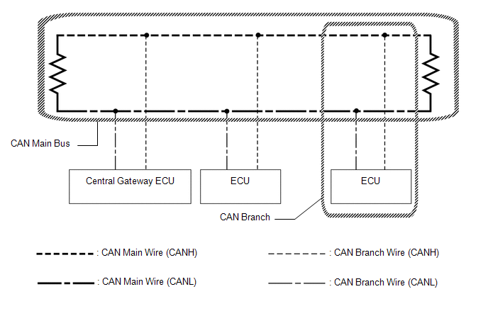
(a) Main bus
(1) The main bus is a wire harness between the two terminating resistors on the bus. This is the main bus in the CAN communication system.
(b) Branch
(1) A branch is a wire harness which diverges from the main bus to an ECU or sensor.
(c) Terminating resistors
(1) Two resistors of 120 Ω are installed in parallel across the ends of the CAN main bus lines. They are called terminating resistors. These resistors allow the changes of the voltage differential between the CAN bus lines to be accurately judged. To allow proper function of CAN communication, it is necessary to have both terminating resistors installed. Since the two resistors are installed in parallel, this results in a measurement of approximately 60 Ω.
ECUS OR SENSORS WHICH COMMUNICATE THROUGH CAN COMMUNICATION SYSTEM
(a) Bus 1
(1) Network gateway ECU
(2) Clearance warning ECU assembly*1
(3) Parking assist ECU*2
(4) Forward recognition camera
(5) Millimeter wave radar sensor assembly
(6) Rear television camera assembly
(7) Blind spot monitor sensor LH*3
(b) Bus 2
(1) Network gateway ECU
(2) ECM
(c) Bus 3
(1) Network gateway ECU
(2) DCM (telematics transceiver)*4
(3) Radio receiver assembly
(d) Bus 4
(1) Network gateway ECU
(2) Skid control ECU (brake actuator assembly)
(3) 4WD ECU assembly*5
(4) Tire pressure warning ECU and receiver
(5) Absorber control ECU*6
(6) Power steering ECU assembly
(7) Steering sensor
(8) Yaw rate sensor assembly*7
(9) Airbag sensor assembly
(10) Occupant detection ECU
(e) Bus 5
(1) Network gateway ECU
(2) Certification ECU (smart key ECU assembly)
(3) Combination meter mirror ECU (headup display)*8
(4) Headlight ECU sub-assembly LH*9
(5) Combination meter assembly
(6) Air conditioning amplifier assembly
(7) Main body ECU (multiplex network body ECU)
(f) Sub Bus 1
(1) Main body ECU (multiplex network body ECU)
(2) Outer mirror control ECU assembly (for driver side)
(3) Outer mirror control ECU assembly (for front passenger side)
(4) Position control ECU and switch assembly LH*10
(5) Multiplex tilt and telescopic ECU
(6) Multiplex network door ECU
HINT:
*1: w/ Intuitive Parking Assist System
*2: w/ Panoramic View Monitor System
*3: w/ Blind Spot Monitor System
*4: w/ Manual (SOS) Switch
*5: for AWD
*6: w/ AVS
*7: w/ TFT Meter Type Combination Meter Assembly
*8: w/ Headup Display System
*9: w/ Automatic Headlight Beam Level Control System
*10: w/ Seat Position Memory System
CIRCUIT DESCRIPTION
(a) The V bus has termination circuit with a resistor of 60 Ω.
(b) The bus 1, bus 2, bus 3, bus 4, bus 5 and sub bus 1 each have termination circuits with two resistors of 120 Ω.
TROUBLESHOOTING REMARKS
(a) DTCs for the CAN communication system can be checked using the Techstream. The DLC3 is connected to the CAN communication system, but no DTCs exist regarding problems in the DLC3 or the DLC3 main lines. If there is a malfunction in the DLC3 or the DLC3 main lines, ECUs on the CAN cannot output DTCs to the Techstream.
DIAGNOSTIC TROUBLE CODES FOR CAN COMMUNICATION SYSTEM
HINT:
See Diagnosis System.
Click here .gif)
HOW TO DISTINGUISH CONNECTOR OF CAN JUNCTION CONNECTOR
(a) In the CAN communication system, the shape of connectors connected to the CAN junction connector which has an earth terminal are the same. The connectors connected to the CAN junction connector can be distinguished by the colors of the bus lines and the connecting side of the junction connector.
HINT:
See Terminals of ECU for bus line color or the shape of connectors.
Click here
 System Diagram
SYSTEM DIAGRAM (a) The CAN communication system is composed of 7 buses. CAN Main Bus Line Terminating Resistor CAN Branch Line * Gateway Function Equipped ECU Bus Monitor ...
 Problem Symptoms Table
PROBLEM SYMPTOMS TABLE HINT:
Use the table below to help determine the cause of problem symptoms. If multiple suspected areas are listed, the potential causes of the symptoms are listed in order of ...
Other materials:
Lexus RX (RX 350L, RX450h) 2016-2026 Repair Manual > Navigation System: Main Body ECU Vehicle Information Reading/Writing Process Malfunction (B15F6)
DESCRIPTION This DTC is stored when items controlled by the main body ECU (multiplex network body ECU) cannot be customized via the navigation system vehicle customization screen. HINT: The main body ECU (multiplex network body ECU) controls the items for the following systems that are customizable ...
Lexus RX (RX 350L, RX450h) 2016-2026 Repair Manual > Airbag System: Front Door Pressure Sensor LH (B167A,B167E)
DESCRIPTION The side collision sensor LH circuit (bus 1) consists of the airbag sensor assembly, door side airbag sensor LH and rear airbag sensor LH. The door side airbag sensor LH and rear airbag sensor LH detect impacts to the vehicle and send signals to the airbag sensor assembly to determine if ...
Lexus RX (RX 350L, RX450h) 2016-{YEAR} Owners Manual
- For your information
- Pictorial index
- For safety and security
- Instrument cluster
- Operation of each component
- Driving
- Lexus Display Audio system
- Interior features
- Maintenance and care
- When trouble arises
- Vehicle specifications
- For owners
Lexus RX (RX 350L, RX450h) 2016-{YEAR} Repair Manual

0.01