Lexus RX (RX 350L, RX450h) 2016-2026 Repair Manual: Precaution
PRECAUTION
NOTICE FOR INITIALIZATION
NOTICE:
When disconnecting the cable from the negative (-) battery terminal, initialize the following systems after the cable is reconnected.
| System | See Procedure |
|---|---|
| LKA /LDA System | |
| Pre-collision System | |
| Intelligent Clearance Sonar System | |
| Lighting System (w/ Automatic Headlight Beam Level Control System) | |
| AFS (Adaptive Front-lighting System) | |
| Parking Assist Monitor System | |
| Panoramic View Monitor System | |
| Power Door Lock Control System | |
| Power Back Door System |
CAN COMMUNICATION SYSTEM TROUBLESHOOTING
(a) Because the order of diagnosis is important to allow correct diagnosis, make sure to begin troubleshooting using How to Proceed with Troubleshooting when CAN communication system related DTCs are output.
Click here .gif)
PRECAUTION FOR STEERING SYSTEM HANDLING
(a) Be careful when replacing parts. Incorrect replacement could affect the performance of the steering system and result in hazardous driving.
PRECAUTION FOR SRS AIRBAG SYSTEM HANDLING
(a) This vehicle is equipped with a Supplemental Restraint System (SRS) which includes parts such as airbags for the driver and front passenger. Failure to carry out service operations in the correct sequence could cause unexpected SRS deployment during servicing and may cause a serious accident. Before servicing (including removal or installation of parts, inspection or replacement), be sure to read Precaution for SRS.
Click here
BUS LINE REPAIR
(a) After repairing a bus line with solder, wrap the repaired part with electrical tape.
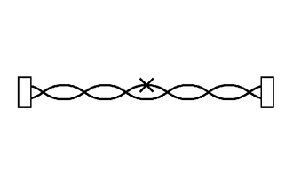
NOTICE:
- The CANL bus line and CANH bus line must be installed together at all times.
- When installing, make sure that these lines are twisted, because CAN bus lines are likely to be influenced by electrical noise if the bus lines are not twisted.
- Leave approximately 80 mm (3.15 in.) loose in the twisted wires around the connector.
- When repairing the CAN bus lines, do not change the length of the lines. (Make sure that the length of the CANH bus line and CANL bus line are the same.)
(b) Do not use bypass wiring between connectors.
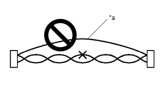
| *a | Bypass Wire |
NOTICE:
- The ability of the twisted bus lines to resist interference will be lost if bypass wiring is used.
- Do not use a twisted pair of wires for bypass wiring.
CONNECTOR HANDLING
(a) When checking resistance with a tester, insert the tester probes from the backside (harness side) of the connector.
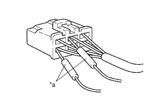
| *a | Tester Probe |
(b) Use service wires to check the connector if it is impossible to check continuity from the rear of the connector.
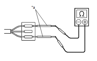
| *a | Service Wire |
PRECAUTIONS FOR INSPECTING OR REPLACING CAN JUNCTION CONNECTOR
(a) If the CAN junction connector is removed from the vehicle for inspection or replacement, make sure to install the CAN junction connector and all wire harnesses to their original locations with tape and the clamps.
PRECAUTIONS WHEN REPLACING A GATEWAY FUNCTION EQUIPPED ECU (SUB BUS MONITOR ECU OR NETWORK GATEWAY ECU) WITH A USED ONE FROM ANOTHER VEHICLE
Body Electrical > Main Body > Utility| Tester Display |
|---|
| Initialization |
| Tester Display |
|---|
| Initialization |
(a) When a gateway function equipped ECU (main body ECU (multiplex network body ECU) or network gateway ECU) that was previously installed on another vehicle is used as a replacement part, it is necessary to initialize the connection information stored in the ECU.
NOTICE:
If the connection information stored in a gateway function equipped ECU that was previously installed on another vehicle is different from the actual ECUs and sensors connected to the corresponding bus, communication DTCs will be stored.
(b) Initialize the connection information of a gateway function equipped ECU (sub bus monitor ECU).
(c) Connect the Techstream to the DLC3.
(d) Turn the engine switch on (IG).
(e) Turn the Techstream on.
(f) Enter the following menus: Body Electrical / Main Body or Central Gateway / Utility
(g) Select Initialization from Utility to initialize the ECU.
PRECAUTIONS FOR WHEN GATEWAY FUNCTION EQUIPPED ECU (SUB BUS MONITOR ECU OR NETWORK GATEWAY ECU) DETECTS COMMUNICATION DTCS FOR ECUS NOT CONNECTED TO THE ECU
(a) Refer to Precautions When Replacing a Gateway Function Equipped ECU (Sub Bus Monitor ECU or Network Gateway ECU) with a Used One from Another Vehicle and initialize the connection information of the ECU.
(b) Clear the DTCs and check that no DTCs are output.
 Parts Location
PARTS LOCATION ILLUSTRATION *1 MILLIMETER WAVE RADAR SENSOR ASSEMBLY *2 SKID CONTROL ECU (BRAKE ACTUATOR ASSEMBLY) *3 ECM *4 FORWARD RECOGNITION CAMERA *5 HEADLIGHT ECU SUB-A ...
 System Diagram
SYSTEM DIAGRAM (a) The CAN communication system is composed of 7 buses. CAN Main Bus Line Terminating Resistor CAN Branch Line * Gateway Function Equipped ECU Bus Monitor ...
Other materials:
Lexus RX (RX 350L, RX450h) 2016-2026 Repair Manual > Telematics System: How To Proceed With Troubleshooting
CAUTION / NOTICE / HINT HINT:
Use the following procedure to troubleshoot the telematics system.
*: Use the Techstream.
PROCEDURE 1. VEHICLE BROUGHT TO WORKSHOP
NEXT 2. CUSTOMER PROBLEM ANALYSIS HINT:
In troubleshooting, check that the problem symptoms h ...
Lexus RX (RX 350L, RX450h) 2016-2026 Repair Manual > Outer Rear View Mirror: Installation
INSTALLATION CAUTION / NOTICE / HINT HINT:
Use the same procedure for the RH side and LH side.
The following procedure is for the LH side.
PROCEDURE 1. INSTALL OUTER REAR VIEW MIRROR ASSEMBLY (a) Engage the 2 guides and claw. (b) Temporarily install the outer rear view mirror ...
Lexus RX (RX 350L, RX450h) 2016-{YEAR} Owners Manual
- For your information
- Pictorial index
- For safety and security
- Instrument cluster
- Operation of each component
- Driving
- Lexus Display Audio system
- Interior features
- Maintenance and care
- When trouble arises
- Vehicle specifications
- For owners
Lexus RX (RX 350L, RX450h) 2016-{YEAR} Repair Manual

0.0133